Generally, water stored in overhead tank is wasted due to over flow ,when the tank is full. Water level alarm using micro-controllers like 8051 and AVR are shown in previous articles.This article shows simple circuits of water level indicator with alarm.
Three circuits were shown here are simple and built using transistors, 555 timer and ULN2003 IC. First let us build a water level alarm using simple transistors.
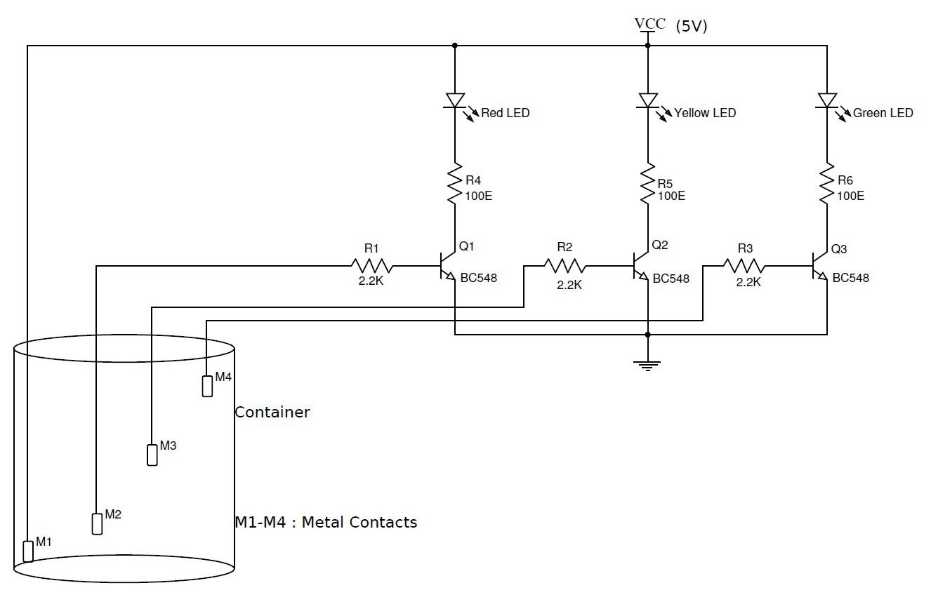
Water Level Indicator Using Simple Transistors
Circuit Diagram
Components Required
- BC548 transistors-Q1,Q2,Q3,Q4
- Resistors R1,R2,R3,R4-2.2kohms
- R5, R6 ,R7 – 100 ohm
- Led – Red(LED3) , Green(LED1) , Yellow(LED2)
- Metal Contacts – M1,M2,M3,M4.
Working
- The circuit is designed to indicate three levels of water stored in the tank: low but not empty, half and full but not overflowing.
- When there is no water in the tank, all the LEDs are off as an indication that the tank is completely empty.
- When water level increases and reaches M2, the contacts M1 and M2 get shorted as water acts as a conducting medium between M1 and M2.
- This will turn on the transistor Q1 and the Green LED starts to glow. As the water level continues to rise and reaches half the tank, M3 will come into contact with water and receives a small voltage from M1.
- As a result, Q2 is turned on and Yellow LED will glow. When the water in the tank rises to full tank, M4 is also shorted with M1 and both Q3 and Q4 will turn on.
- The Red LED glows and also an alarm is made by the buzzer as an indication that the tank is full and the water pump or motor can be turned off.
Note:This circuit does not show a buzzer.Connect a Buzzer,resistor and transistor in series and connect this in parallel to the last LED.
Water Level Alarm Using 555 Timer
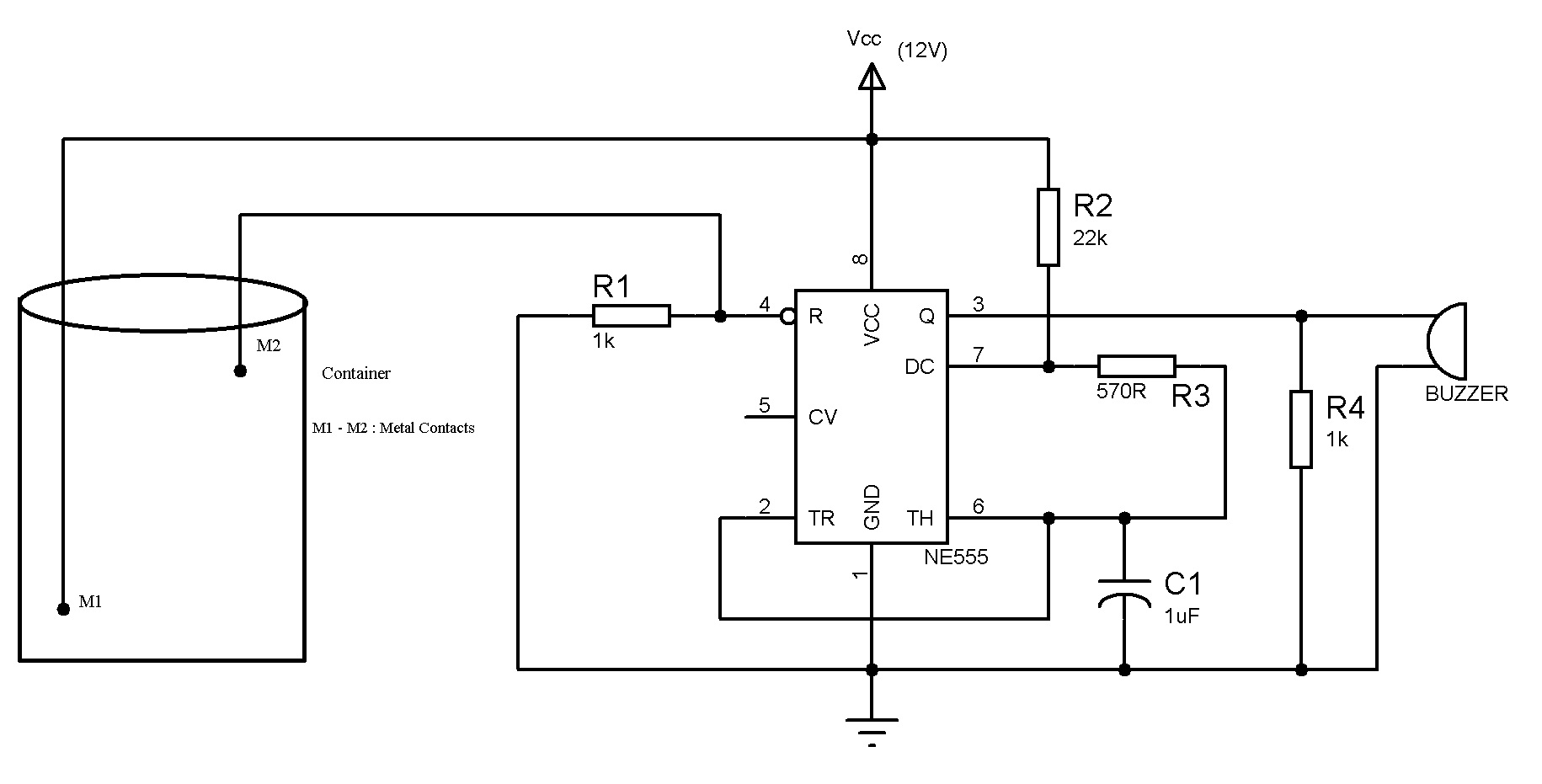
Here is the circuit using 555 timer IC.
Circuit Diagram
Components Required
- NE555 Timer
- Resistors
- R1,R4-1K
- R2-22k
- R3-570 Ohm
- Capacitor- 1UF
- Buzzer
- Connecting wires
Working
The circuit uses a 555 timer in astable mode with R1=22k ohms, R2= 570 ohms and C1=1 uF. The frequency of the given astable circuit is around 62 Hz.
The two probes which are shown in the circuit should be kept at the high level for the water. The distance between the probes should be less than a few centimetres to ensure that the conduction between the probes will take place when water is touched to these probes.
When the water level rises to the height of the probes, then the 555 circuit will get enabled and the output of the 555 timer produces a square wave output with a frequency of about 62 Hz. This output is given to the buzzer.
The logic Implemented in this circuit is, 555 timer is enabled when its reset pin is connected to logic high. But initially it is connected to ground. When the water level is maximum this pin is enabled and this drives the 555 timer into astable mode.
Water Level Indicator and Alarm Using ULN2003
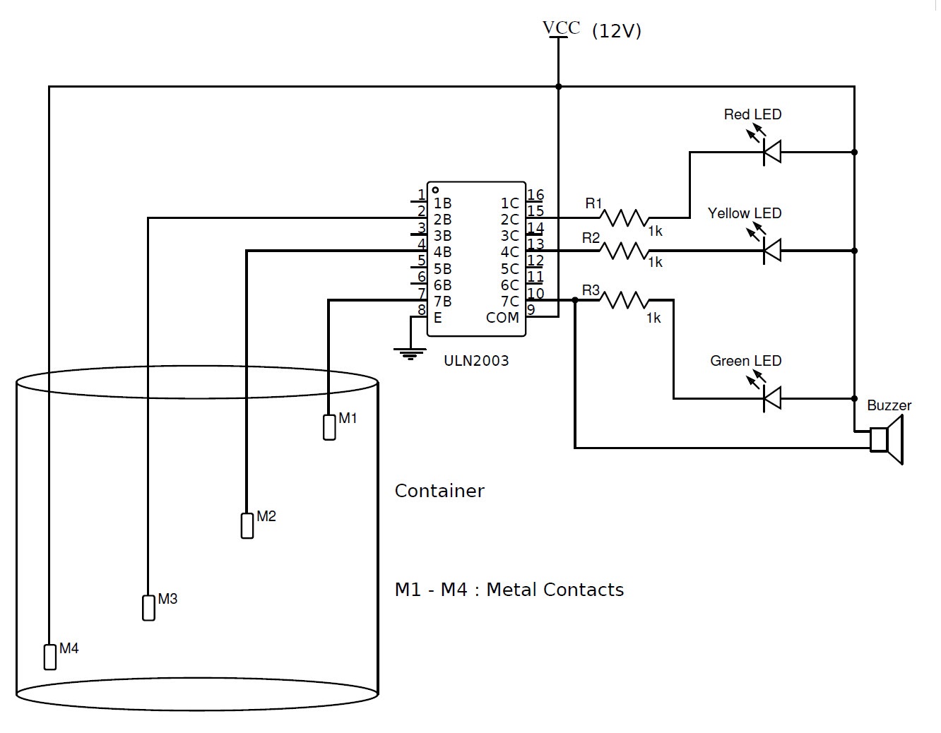
One can implement this circuit using simple ULN2003 IC.IC ULN2003 consists of an array of seven Darlington transistor pairs.
Circuit Diagram
Components Required
- L1-L3-LEDs
- R1-R3-1k ohm
- M1-M7-Metal Contacts
- ULN2003 IC
Working
- This circuit can be used to indicate three levels of water in tanks.
- When metal contact is reached ,each Led starts glowing.
- When the tank is full buzzer starts ringing along with this all LEDs are ON.
Also Read the Post: Water Level Indicator Using AVR Microcontroller

80 Responses
i need water level contact no or nc
2 no tank 1st is botam and second is up
wean bottom tank water level hi this time
give “nc” contact to motor wean upar tank
full this time all system are stop.
pleas i received circuit dayogrm
1st refrains ic 555
thank you..
Thank you sir
Good idea sir
What must be wattage of the Resistors.
I think Quaqrter watt will do.
Whats your say.
What current I supply this circuit …AC or dc?
dc
you will use dc current
can give me a list of component??
you can check the circuit diagram for required components
Please check the circuit diagram for components..All the components with their ratings are provided in the circuit diagram itself
what are the components
list
sir, please tell me what is the project code of every project………….
what is the polarity of loudspeaker
There no polarity for speaker
what are the source given in this circuit?and what is palace pls tell me
a 9v battery is connected to 8th pin.
transister using postive negative what place given please tell me
Any Ideas on how this Circuit could be tweaked slightly in order to use it for my BTEC?
How to increase the frequency of the speaker when the water rises
What is the rating of speaker?
How should it to be connected in the circuit?How we connect a switch in the circuit?
Here we used 8 ohms speaker…Please check the circuit diagram to know how to connect speaker… Where and why do you want to connect the switch??
how can i implement the water level alarm in a tank which is placed in the vehicle and also i want to cut the supply automatically when tank is filled
in water level alarm project where should i place the supply to the circuit
Supply is given to the 8th pin
Can I use led inplace of speaker
yes
please where will I connect the power
can i use a buzzer instead of speaker????
HA DEFINITELY. BUZZER IS SMALL LOAD COMPARED SPEAKER.
Sir how to connect pump motor for auto on/off in water level indicator
Sir can i connect an led instead of the speaker
water level indicator using 555 timer is not working ….what can i do
water level indicator using transitor .where will power is connect
Connect the power supply to M1.
please explain the the principle behind it.so,that we can something cool with it……!!!!
thamk you sir…..!!!!
plz share a video … so that we can see it
please i need help ooooooooo how do you write a proposal on water level indicator for your project
What the resistance (Ohms) and the wattage of the speaker used?Also what is the wattage of the resistors?
HOW THE CONTACT TYPE CAPACITIVE WATER LEVEL SENSOR CAN BE CONNECTED TO ARDUINO BOARD UNO BOARD? I USED SS CONTACT TYPE SENSOR.
How are you determining the resistances for the the ic 555 timer?
do like a wi-fi wireless water level indicator? that’s better for mainly cities
what are the disadvantages of water level indicator
partianing the circuit where you used transistors for the water indicator circuit, how can i make the red LED turn off while the amber led stays on, cause i Want the amber to indicate stable mode, so when its in stable mode the red LED turns off but when it goes below the stable mode, the red LED turns on, what can i do pls. thanks
What is the metal contact used to detect the water?
What are the metal contacts used to detect the water?? THANK YOU!!
Excuse me please can i know the name of the publisher of this article, want to include it in my proposal, thank you
can i apply this circuit on pcb?
which metal can be used as m1,m2,m3,m4
You can use any conducting wire.
Thanks,this diagrams are helps me lot.this worked perfectly.
What changes do i make so that only one of the bulb glows
Water Level Detector Using Simple Transistor.
why should we use transistors if we can directly connect led with Current Limiting Resistor?
Transistor gives current gain
Can we use 9v battery instead of 12v in ULN2003 IC ?
I need unl2003 water level controller. Not indictor. Please anyone help me.
This is one of the best and simple project without microcontroller .
Please may I know the objectives of this project?
What are the limitations of the project. Can it work for any water level measurement?
My requirement is that after every 15 minute the motor should run for 2 minutes then halt then again start after 15 minute.
Please provide me the details for this circuit…
If the circuit is places near the tank how can we see that LEDs are glowing or not and we are unable to hear sound of a buzzer.can u please explain me
Wherever your indicator is required from that place to the tank you need to run the tank wires
can we place IC555 on the PCB board????
PLEASE GUYS HELP ME .ITS OK IT PLACED ON THAT .IT IS NOT AN ISSUE. BUT IN 555 TIMER WE KNOW WHEN WATER REACHES THE PEAK THE BUZZER WILL ON.BUT HOW TO KNOW THE TANK S EMPTY. WHEN OUR ISMOTOR IS ON IN ORDER TO FILL THE TANK. 1STLY WE KNOW RIGHT.HOW MUCH WATER PRESENT IN WATER LEVEL.
THANK U FOR UPLOADING GOOD PROJECT LIKE THIS. I GET A SMALL DOUGHT ABOUT USING 555 TIMER CIRCUIT . IN THAT THE BUZZER WILL RING WHEN WATER LEVEL REACHED TO PEAK LEVEL .BUT HOW TO KNOW THE TANK IS EMPTY. FOR KNOWING THAT WE HAVE TO KEEP ONE
THRESHOLD LEVEL .HOW IT POSSIBLE IN THIS CIRCUIT.PLEASE GIVE RESPONCE QUICKLY.
Tks sir for the diagram, gbu
What type of metal contacts should be used?
Can this thing use in tap water?
Can u say the applications of this experiment
is it dosent requires any programming
Here we used only IC’s and Transistors as a major components. So, no need for any programming.
What is the current for the 12v for the above circuit if i use an smps
I have assembled the first circuit and powered with 12 Volt supply; On switching on the circuit all the led are dimmly lit. Why it is so happening. Kindly enlighten me and give me the rectification for this.
first of all, have you modified the circuit to work with 12V??
if yes, then try to connect 10kΩ resistors to all the base of the transistors to ground.
Water Level Indicator Using Simple Transistors
Connect a Buzzer, resistor and transistor in series and connect this in parallel to the last LED.
Could you please add this to the diagram, I need to see it, to understand
Thank you
Does people will get shocked when touching the water??
NO.
The amount of current flowing through the water is very low. So, you won’t even feel it.
I want to use ULN2003 as water indicator circuit. I want to combine my existing water lever controller with new indicator circuit. my current controller circuit uses 0v as input from tank not the vcc to avoid scale formation on the contacts. This means 0v wire is given to tank water and signal from different level is received to glow the LED and trigger the motor SSR. how to use ULN2003AN to receive 0V as input on base as signal from tank and glow the LED at different water level?
if you already implemented this kind of project I suggest you to upgrade this project using magnetic relays instead of using electrodes.
Your connection video is not clear. not clear means dont know where the wire connected.so can you please upload a new video or clear detail about connection.
can you please explain the working principle and the duty of resistors one by one thanks
for the water lever alarm using 555 timer