In this tutorial, we will learn about the basics of Thyristor. We will see a brief origin of Thyristor (from Thyratron and Transistor), a small list of applications of Thyristor.
Introduction
Nowadays, many electromechanical or electrical equipments from household appliances, such as uninterrupted power supplies to industrial power and motor control equipments , consist of power electronic circuits, in which Thyristors play an important role as solid-state switching devices.
The conventional methods of power control involve use of variable tap-changing transformers, shunt and series regulators to produce the variable voltage in steps. But these are cost effective and inefficient. Later, magnetic amplifiers are invented to produce the static control of power with a greater reliability.
However, due to the bulkiness of the controllers and less efficiency, these are limited to certain applications.
A Brief History of Thyristor
The development of power control with electronic methods is started with the use of thermonic and gas-discharge valves. These devices include mercury arc converters and thyratrons and ignitrons. The thyratrons are gas-filled triodes used particularly for switching heavy currents.
With the rapid development in semiconductor technology, miniaturization of electronic circuits replaces these thermonic valves and gas-discharge valves results to use power diodes and power transistors in many industrial applications.
A new trend in fabrication technology developed thyristors which exhibit similar characteristics of gas tube thyratrons. Thyristor name is derived by the combination of two words as thyraton and transistor. Due to the improved reliability, increased temperature performance and lower manufacturing costs, these thyristors are being widely used for many applications.
The first prototype of thyristor was introduced in 1957 by the General Electric company. Since then, with the fabrication developments and adaptability to many industrial applications, other devices with similar characteristics were introduced which comes under the thyristor family.
The basic material of the device is silicon and hence these are named as Silicon Controlled Rectifiers (SCR’s). However, generally considered that , SCR is an oldest member of thyristor family.
Structure of Thyristor
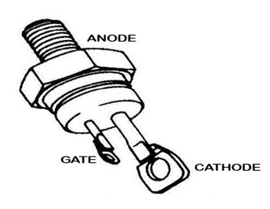
Thyristor is a four layer (alternate P and N type materials) three terminal device , commonly used in adjustable rectification circuits. These terminals are anode, cathode and gate. The two terminals anode and cathode are connected in series with the load and handles the current through it by controlling the current through the gate terminal.
Thyristors are designed to handles the high energy levels (of Voltage and currents) approximately greater than 1 KV and 100 A. Even high rated SCR can be switched or controlled by low voltage supply (about 10 W and 1A). Hence a tremendous control capability is possible with SCR’s or thyristors.
Difference Between Thyristor and Thyratron
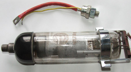
Image Source:https://www.tuopeek.com/image2/thyratron.jpg
Before the invention of thyristor or SCR, thyratrons are popularly used for industrial control applications. Popular forms of this device are arc converters which use thyratrons for both rectification and inversion. Thyratron is a gas-filled tube consisting of three terminals namely anode, cathode and grid. With the positive voltage between the grid and cathode, thyratron is switched ON. Some of the differences of Thyristor or SCR and thyratron tube are listed below.
- An SCR or Thyristor needs one main supply and one control supply or signal, whereas thyratron needs a large supply voltage between anode and cathode terminals and one separate filament supply. And some thyratrons need additional power supply for auxiliary diodes.
- Thyristors can be operated with a wide range of frequencies, whereas thyratrons are limited to a frequency range of 1 KHz because arc ionising and deionising times are relatively larger in thyratron.
- The internal losses of the SCR are much smaller than thyratrons because the anode to cathode arc voltage drop in thyratron is higher which is inversely proportional to the molecular weight of the gas used.
- Turn ON and Turn OFF times of thyristor are smaller compared to thyratron that has larger times due to the gases present in the inter electrode region.
- To avoid any unwanted flash-overs and arc-backs sufficient spacing must be provided between the anode and cathode terminals of a thyratron (Due to a large anode to cathode voltage) compared to thyristors. Therefore thyratrons are bulkier than thyristors (which has reduced size and weight).
- Thyristor is more reliable than thyratron.
- The life of thyristor is greater while the thyratron has a shorter life span.
- Thyratron is a voltage controlled device, whereas thyristor is a current controlled device.
Difference Between Thyristor and Transistor
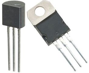
Both thyristor and transistors are three terminal semiconductor switching devices used for many switching applications due to their advantages like smaller size, high efficiency and low cost.
Even though the transistors are available with high voltage and current ratings termed as power transistors, there are some differences between these two devices which are listed below. However, both the power transistors and thyristors have thier own applications in which they are extensively used.
For a given size, thyristor have much higher current and voltage ratings than transistors when fabrication is considered.
- Thyristor is a four layer device whereas transistor has three layers.
- Once the gate triggered with one pulse, the SCR or thyristor remains turn ON (also called as the regenerative action of thyristor) until it is turned OFF through different techniques. But transistor needs a continuous base current to remain in conduction state.
- Thyristor is used only as a switching device (either to turn ON or turn OFF) where as for many applications, transistor need to be operated in active region.
- Thyristors are rated in the range of kilo watts. On other hand power transistors are rated in the range of several 100 watts.
- The internal power losses in the power transistors are higher than thyristors.
Types of Thyristors
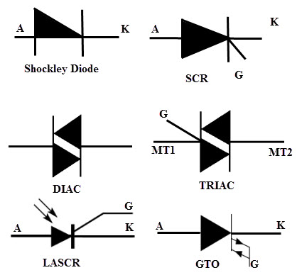
Thyristors family devices are classified into different types which can be employed for different applications. With triggering signal at the gate terminal causes to turn ON of thyristor and its turn OFF operation depends on the power circuit configuration. So the external controllability is only to turn ON in case of thyristors.
However some thyristors (from 12 to 19 in the below list) have externally controllable circuitry for both turn ON and OFF the thyristor through gate or base terminal. Some of the types of thyristors include
1. Phase Controlled Thyristors
2. Asymmetrical Thyristors (ASCRs)
3. Inverter-grade Thyristors (fast switching speed SCRs)
4. Reverse Conducting Thyristors (RCTs)
5. Bidirectional Diode Thyristors (DIACs)
6. Gate Assisted Turn-off Thyristors (GATT)
7. Bidirectional Triode Thyristors (TRIACs)
8. Silicon Control Switch (SCS)
9. Silicon Bilateral Switch (SBS)
10. Silicon Unilateral Switch (SUS)
11. Light Activated Silicon Controlled Rectifiers (LASCRs)
12. Static Induction Thyristors (SITHs)
13. Gate Turn OFF Thyristors (GTOs)
14. Static Induction Transistors (SITs)
15. MOS Controlled Thyristors (MCTs)
16. Field Controlled Thyristors (FCTs)
17. MOS Turn OFF Thyristors (MTOs)
18. Emitter Turn OFF Thyristors (ETOs)
19. Integrated Gate Commutated Thyristors (IGCTs)
Applications of Thyristors
Due to the high switching speed and high power handling capacity thyristors are widely used in alternating current control applications rated at a higher level of voltages and currents. By the appropriate gate signal of the thyristor, average output power is controlled using the thyristors.
And also, when the thyristor is forward biased, a delayed gating signal can produce the phase control of the output. This phase controllability can produce less average voltage than the average voltage produced by the uncontrolled rectifier.
This is the most important application of the thyristor. The following are the applications of thyristors in which it is used for power control.
- Speed Controllers of AC and DC motors
- DC and AC circuit breakers
- Illumination (light dimmers) and temperature controllers
- Pressure control and liquid level regulators
- Variable voltage AC to DC rectifiers
- Variable frequency DC to AC inverters
- Variable frequency AC to AC converters or Cyclo converters
- HVDC, HVAC transmission and static VAR systems.
- Resistive welding and induction heating systems etc.

3 Responses
thank you.
I need to switch on 1200v DC it is capacitor dumping which thyristor can use
Interesting