In this tutorial, we will learn about Sound Transducers. Two common Sound Transducers are Microphones and loud speakers.
Introduction
Sound is a generalized term given to acoustic waves which are a type of longitudinal waves that propagate by compression and decompression in adiabatic process. The frequency range of acoustic waves is between 1 Hz to tens of thousands of Hz. In this huge range, human can hear between 20 Hz to 20 K Hz.
Audio or sound transducers are of two types: input sensors or sound to electrical transducers and output actuators or electrical to sound transducers. The example of input sensor is a microphone and for output actuator is a loudspeaker.
Sound transducers can detect and transmit sound waves. If the frequency of the sound wave is very low, then they are called infra – sound. And if the frequency of sound wave is very high, then they are called ultra – sound.
What is Sound?
Sound and vibration are interconnected as sound is associated with mechanical vibration. Many sounds are caused by vibration of solids or gases. According to ANSI, sound is defined as “oscillation in pressure, stress, etc., propagated in a medium with internal forces or superposition of such propagated oscillation.” Sound wave is the waveform caused by a vibration.
This waveform causes an identical vibration to be set up in any material affected by the sound wave. In order to transmit sound waves, a medium that can be vibrated is needed. A vibrating object or material compresses the surrounding air molecules and rarefies them. There is no transmission of sound waves through vacuum.
When sound is transmitted, it has three important wave parameters: velocity or speed, wavelength and frequency. These characteristics are similar to that of an electrical waveform. The frequency and the wave shape of the sound are determined by the origin of the sound or the frequency and wave shape of the vibration that causes the sound.
The velocity and wavelength of the sound are dependent on the medium that transmits the sound waves. The relationship among the three parameters velocity, wavelength and frequency is shown below.
Frequency (f) = Velocity (m/s) / Wavelength (λ)
The units of frequency are Hertz (Hz).
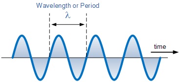
Image Resource Link: electronics-tutorials.ws/io/io46.gif
The velocity of sound in a given material depends on the density and elasticity of the material. Hence the velocity of sound is higher in solids and low in high pressure gases.
Objective measurement of sound waves makes use of intensity of receiving surface measured as the number of watts of sound energy per square meter. The ear has a non – linear response and the sensitivity vary with the frequency of sound.
The frequency range over which sound can be detected by the human ear is between 20 Hz to 20 kHz. The response of the ear is maximum in the region of 2 kHz.
What are Sound Transducers?
A sound transducer is a device that can convert Sound Signals into electrical signals or electrical signals into sound signals. In the former case, they are called as Input Sound Transducers and a Microphone is an example for this case.
In the latter case, they are called as Output Sound Transducers and a Speaker is an example.
Microphone (Input Sound Transducer)
The audio or sound to electrical energy transducer is the microphone or simply called as mic. A microphone produces electrical analog signals that are proportional to the sound waves acting on its diaphragm. Microphones are classified by the type of electrical transducer they use. In addition to the transducer, microphone uses acoustic filters and passages whose shape and dimension modify the response of the overall system.
The characteristics of a microphone are both electrical and acoustic. The sensitivity of a microphone is expressed as mV of electrical output per unit intensity of sound wave. The impedance of microphone has the considerable importance. A microphone with high impedance has a high electrical output while the one with low impedance is associated with low output. The high impedance makes the microphone susceptible to hum pick up.
Directionality of the microphone is also an important factor. If the microphone is used in sensing of the pressure of sound waves, then it is Omni – directional i.e. it picks up sound arriving from any direction. A microphone is directional if it responds to the velocity and direction of the sound wave.
The type of sound transducer does not necessarily determine the operating principle as pressure or velocity, but the construction of the microphone is the most important factor.
Some of the most common types of microphones are: Carbon microphone, Moving Iron microphone, Moving Coil microphone, Ribbon microphone, piezoelectric microphone and electret capacitor microphone.
Carbon Microphone
The carbon microphone was the first type of microphone to be developed for usage in telephones. Now they are replaced by electret capacitor microphones. Carbon microphone uses granules of carbon held between a diaphragm and a backplate.
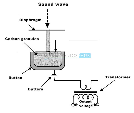
When the granules are compressed, the resistance between the diaphragm and the backplate drops considerably. The vibrations of the diaphragm, which are the result of the sound wave incident on it, can be converted into variations of resistance of granules. The microphone requires an external power supply as it does not generate voltage.
The main and only advantage of carbon microphone is that it produces an output that is huge by microphone standards.
The disadvantages include poor linearity, poor structure that causes multiple resonances in the audio range and high noise level as the resistance of the granules alter even in the absence of sound.
Moving Iron Microphone
Moving iron microphones are also called as Variable Reluctance Microphones. Moving iron microphone uses a powerful magnet. The magnetic circuit contains an armature made of soft iron, which in turn is connected to a diaphragm. As the armature moves, the magnetic reluctance of the circuit alters and this in turn change the total magnetic flux in the circuit. The magnetic circuit in this type of microphone makes the instrument heavier.
Moving Coil Microphone or Dynamic Microphone
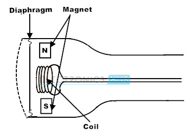
Moving coil (Dynamic) microphones use a constant flux magnetic circuit. In this circuit, the electrical output is generated by moving a coil of wire in the circuit which is attached to a diaphragm. This whole arrangement is in capsule form which makes this a pressure operated microphone rather than velocity operated.
The coil moves in response to movement of the diaphragm as the sound waves hit the diaphragm. By applying Faraday’s Law of Electromagnetic Induction, a voltage is induced in the coil due to the movement of the coil in the magnetic field. Maximum output occurs when the coil reaches maximum velocity between the peaks of sound wave so the output is 900 out of phase with the sound.
The internal view of a Dynamic Microphone is shown below.
The range of the movement of the coil is very small as the size of the coil is small. Hence the linearity of moving coil type microphones is excellent. Due to the low impedance of the coil, the output is considerably low and hence amplification of the signal is required.
The inductance of the coil in moving coil microphones is less and therefore they are less susceptible to hum pick up from mains. The construction of moving coil microphone resembles that of a loudspeaker in reverse.
Ribbon Microphone
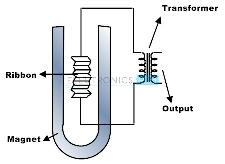
The principle of operation of a ribbon microphone is derived from moving coil microphone and the change is that the coil has been reduced to a strip of conducting ribbon. The signal is taken from the ends of the ribbon.
An intense magnetic field is used so that the movement of the ribbon cut across the maximum possible magnetic flux is possible. This generates an output with its peak value at 900 out of phase to the sound wave.
The internal view of ribbon microphone is shown below.
Ribbon microphone is a velocity operated microphone. Ribbon microphones are used in situations where directional response is important. The main application of this type of microphone is in voice commentary in noisy surroundings.
The linearity of ribbon microphones is very good and its construction makes it inevitably a low output device. In order to raise the voltage level and the impedance level, ribbon microphones are usually equipped with transformer. Good quality ribbon microphones are expensive items. The directional qualities of this microphone are suitable for stereo broadcasting.
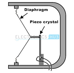
Piezoelectric Microphone
The advantage of Piezoelectric Microphone over other type of microphones is that it is not confined to use in air but can be bonded to solid and also immersed in a non – conducting liquid. Piezoelectric transducers can be used at ultrasonic frequencies and some are used in the high MHz region.
Piezoelectric transducers consist of crystalline material. When the crystal is strained by sound waves, the ions of the crystal are displaced asymmetrical way. Originally, Rochelle Salt Crystal is used as crystalline material in piezoelectric microphones and this crystal is coupled to a diaphragm.
The output voltage and impedance are high, but the linearity is poor. Now a day, synthetic crystals are used over natural crystals. Barium Titanate is the synthetic crystal used for frequencies up to hundreds of KHz.
The figure of piezoelectric microphone is shown below.
Capacitor Microphone
Capacitor microphone consists of two surfaces: one is a conductive diaphragm and other is a backplate and the electric charge between the two surfaces is fixed. When the sound wave hits the diaphragm, the vibrations cause a variation in capacitance.
As the charge is fixed, the variation in capacitance causes a voltage wave. Output depends on the spacing between the plates. Output is greater for given amplitude of sound when the spacing between the surfaces is smaller.
The structure of a capacitor microphone is shown below.
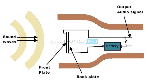
Capacitor microphone is pressure operated device. In order to provide the fixed charge, a voltage supply is needed. This voltage is called Polarizing voltage. The capacitor microphones provide linearity in operation and also provide very good audio signals.
To avoid polarizing voltage, an electret is used. An electret is an insulating material with permanent charge. It is electrostatic equivalent of a magnet. In electret capacitor microphones, one of the plates of the capacitor is a slab of electret and the other is a diaphragm. As the electret provides a fixed charge, there is no need for voltage supply.
Speaker (Output Sound Transducer)
The use of microphone is little unless there is a transducer for opposite direction. The transducers like speakers, buzzers and horns are output sound actuators that can produce sound from an input electrical signal. The function of a sound actuator is to convert electrical signals into sound waves with a close resemblance to the original input signal to a microphone.
Earphones are one of the simpler output sound transducers which have been used long before than microphones were. Earphones were used with a Morse Key machine in electric telegraphs. After the development of microphones, the combination of input and output sound transducers leads to a numerous inventions including telephone. The task of an earphone is simple and as it is placed near the ear, the power requirements are also very less, generally in the order of few milliwatts.
Since the required output is less, earphone uses a small diaphragm. A loudspeaker, unlike earphone, is not pressed against the ear, but rather the sound waves are launched into space. Hence the construction, principle and power requirement of a loudspeaker are a little bit different.
Loudspeakers are available in a variety of sizes, shapes and frequency ranges. The transducer of a loudspeaker system is called as Pressure Unit as it transforms complex electrical signals into air pressure. In order to achieve this, a loudspeaker unit consists of a motor unit which transforms input electrical waves into vibrations and a diaphragm that moves sufficient air in order to make the vibrating effect audible.
For each type of microphone, there is a corresponding loudspeaker. Some of the common types of speakers are: moving iron, moving coil, piezoelectric, isodynamic and electrostatic.
Moving Coil Loudspeaker or Dynamic Loud Speaker
The moving coil principle is used in majority of loudspeakers and earphones. Moving coil loudspeakers are also called as Dynamic Loudspeakers. The operating principle of a moving coil loudspeaker is exactly the opposite to that of a moving coil microphone.
It consists of a coil of fine wire called the voice coil that is suspended in a very strong magnetic field. This coil is attached to a diaphragm like paper or Mylar cone. The diaphragm is suspended on its edges to a metal frame.
The internal structure of a moving coil loudspeaker is shown below.
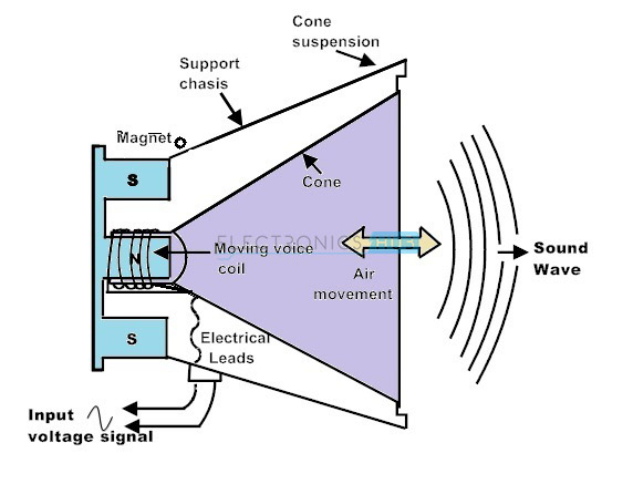
When the input electrical signal passes through the coil, an electromagnetic field is produced. The strength of this field is determined by the current flowing through the coil. The volume control setting of the driver amplifier determines the current flowing through the voice coil. The magnetic field produced by the permanent magnet is opposed by the electromagnetic force which is produced by the electromagnetic field.
This causes the coil to move in one direction or the other determined by the interactions between north and south poles. The diaphragm, which is attached to the coil, moves in tandem with the coil and this causes a disturbance in the air around it. These disturbances produce a sound. The loudness of the sound is determined by the velocity at which the cone or diaphragm moves.
Driving a Speaker
The range of frequencies which human ear can hear is between 20 Hz to 20 KHz. Modern loudspeakers, headphones, earphones and other audio transducers are tailored to operate in this frequency range.
However, for High Fidelity (Hi – Fi) type audio systems, the response of the sound is split up into smaller sub – frequencies. This improves the overall efficiency and sound quality of the speaker. The low frequency units are called as woofers and the high frequency units are called as tweeters.
The units for mid – range frequencies are simply referred to as mid – range units.
The generalized frequency ranges and their terminology are mentioned below.
Sub – woofer — 10 Hz to 100 Hz
Bass — 20 Hz to 3 kHz
Mid – range — 1 kHz to 10 kHz
Tweeter — 3 kHz to 30 kHz
In multi speaker Hi – Fi systems, there are separate woofer, mid – range and tweeter speakers with an active or passive crossover network to accurately split and reproduce the audio signal by all sub – speakers.
A simple circuit to drive a speaker is shown below.
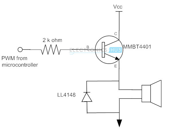
The transistor is in emitter follower configuration. The PWM signal from a microcontroller provides an AC signal to the base of the transistor. The emitter follower configuration gives the AC signal to the speaker by amplifying current. The diode acts as a filter.
A multi speaker design is shown below.
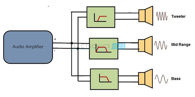
There are three types of drivers: woofer driver, mid – range driver and tweeter driver. A simple audio amplifier circuit is shown below.
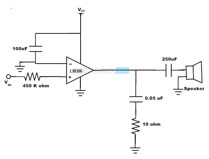
Based on the filter circuit used, the amplifier can be used to drive a woofer or mid – range or tweeter speaker.
Some of the other types of output transducers are mentioned below.
Piezoelectric Loudspeakers
Generally, tweeters are manufactured using piezoelectric principle. The diaphragms are made of piezoelectric plastic sheets. When a voltage is applied between the faces of the diaphragm, it shrinks and expands according to the signal. By shaping the diaphragm as a part of the surface of a sphere, the shrinking and expanding can be converted into movement that will move the air.
Electrostatic Speakers
Electrostatic speakers consist of a conductive diaphragm placed between two electrically conductive plates. The conductive plates are charged positive and negative respectively. When an audio signal is connected, the diaphragm switches between positive and negative charge. The diaphragm is drawn towards the oppositely charged plate depending on its charge. This causes the air in front of it to vibrate.
