Sound is a phenomena that is a result of vibration of materials. Sound is characterized as a mechanical wave that carries mechanical energy.
For the transmission of this energy between transmitter and receiver, presence of a medium is necessary. The medium can be solids, liquids or gases.
The sound energy travels by causing disturbance in the medium it is travelling and this is called propagation of sound waves. Under normal conditions, the velocity of the sound is 330m/s.
SONAR or Sound Navigation and Ranging is a non-contact distance measuring technique generally used in submarines.
In this technique, a high frequency sound wave is transmitted by a transmitter and the reflected echo from a target is captured by a receiver.
As the velocity of the sound wave is known, by measuring the time of travel, the distance between the source and the target can be calculated.
Depending on the frequency of the sound wave, the SONAR can be either Infrasonic or Ultrasonic. Ultrasonic sensors produce sound waves with frequencies higher than the audible range (20Hz to 20 KHz) i.e. greater than 20 KHz. In case of an infrasonic sensor, the frequency of sound wave is less than 20Hz.
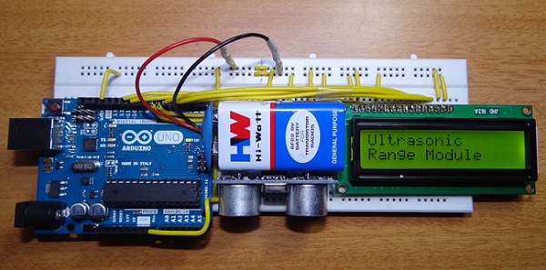
In this project, a Portable Ultrasonic Range Meter is designed which can be used to measure distance of a target in non-contact fashion. The project is based on Arduino, Ultrasonic Sensor and an LCD display.
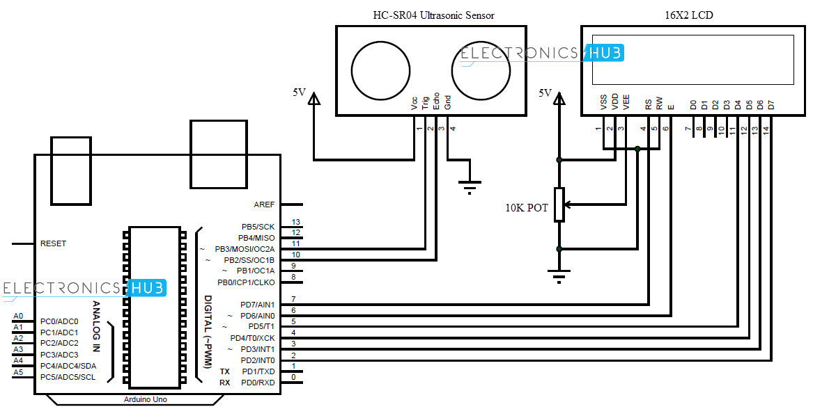
Portable Ultrasonic Range Meter Circuit Diagram
Hardware Required
- Arduino Uno
- Ultrasonic Sensor HC-SR04
- 16X2 LCD Display
- 10KΩ POT
Circuit Design of Ultrasonic Range Meter
The circuit consists of Arduino Uno, which is the brain of the project, an Ultrasonic sensor and an LCD display to instantaneously display the results. The design of the circuit is very simple and is explained below.
Of the available 14 I/O pins on Arduino, we use 8 pins in this project. 2 pins are used for Ultrasonic sensor and other 6 pins are used to control the LCD.
The 4 pins of Ultrasonic sensor are Vcc, Gnd, Trig and Echo. Trig is connected to Pin 11 of Arduino and Echo is connected to Pin 10. With respect to Arduino, Pins 10 and 11 are input and output respectively.
Pins 15 and 16 (LED+ and LED-) of the LCD are backlight pins. They are connected to Vcc and Gnd respectively (not shown in circuit diagram).
Four data pins of LCD are used to display the information. Pins 11, 12, 13 and 14 of LCD (D4 – D7) are connected to pins 5, 4, 3 and 2 of Arduino.
Pins RS and E (pins 4 and 6) of LCD are connected to pins 7 and 6 of Arduino respectively while RW (pin 5) is connected to ground.
Pins 1 and 2 (Vss and Vdd) are connected to ground and Vcc respectively. In order to control the contrast of the LCD display, pin 3 (VE) of LCD is connected to the wiper of a 10 KΩ POT with the other terminals of POT connected to Vcc and Gnd.
Working
Ultrasonic sensor is the main module in the range meter circuit. An ultrasonic sensor consists of an ultrasound transmitter and a receiver. The transmitter sends a sonic burst of 8 pulses at 40 KHz frequency.
This signal hits the target and the echo is received by the receiver module. By measuring the time between the events of sending the pulse and receiving the echo, the distance can be calculated.
The ultrasonic sensor used in this project is HC-SR04. It can be used to measure distance in the range of 2cm to 400cm with accurate readings.
The sensor module consists of 4 pins: Vcc, Gnd, Trig and Echo. When the Trig pin is high for a duration of at least 10µs, the ultrasonic sensor sends the ultrasound signals. The Echo pin is high from the moment of sending the signal and receiving it.
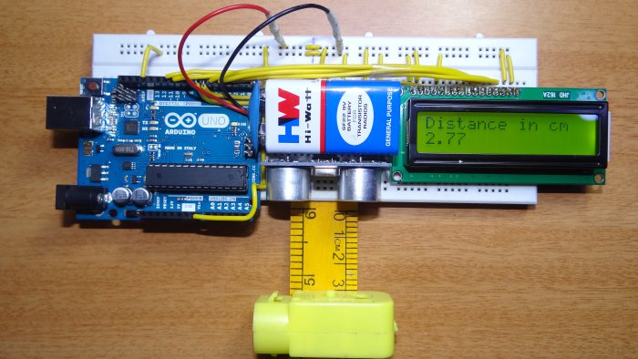
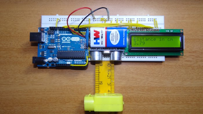
This duration for which the Echo signal is high is calculated by Arduino as per the code and is converted to distance in centimetres. The same data is displayed on the LCD.
Arduino continuously sends the Trig signal and the distance of the target can be measured continuously without any delay.
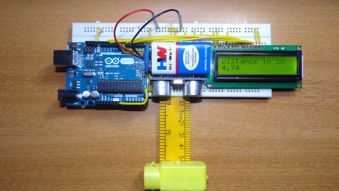
As the power requirement of the circuit is very less, the whole system can be powered by a 9V battery and can be used as a Portable Range Meter.
Download Code
Note
- This circuit can be used as a simple distance measuring device with non-contact technique.
- A battery can be used to power the device to make it portable and an ON/OFF switch can be used to conserve the battery life.
- The use of LCD in the design makes the circuit to instantly display the distance.
- A simple change in code may result in additional information like distance in different metrics, time, date etc.

17 Responses
codes for this? pls msg me tnx!
Please sir give me code… Thanx
I need the codes for this
Download code from the post..
How i download codes?
Please click on download Code link…Code will be downloaded
is it possible to connect a Bluetooth headset with this device to listen the distance ?? please help if you can
Can you or anyone please explain the code ?
Why is there a led in pin 13 in the code ? I don’t see any led in the circuit diagram nor in the video.
Hi, We thought of using an LED as a warning light (if the distance is less than 5 cm, something like that). But we didn’t and made no changes to the code. Ignore the LED initialization. Also, the 13th pin on Arduino has a built in LED.
There is a I build led on Arduino board……that is the yellow light…..
Have you tried using this for distance greater than 5 cm? Like 10 meters?
Hi,
I am very new to these projects, can you please guide me, how can I install your code into board.
-Girish
Is these simulation as possible or not without using bread board
If you meant software simulation, then I think it is not possible.
Which pin is connected to arduino pin no. 13?
Pin 13 is not connected to anything (externally).