In this tutorial, we will take a brief look at two important Combinational Logic Circuits called Multiplexer and Demultiplexer.
A Multiplexer is a circuit that accept many inputs but gives only one output. A Demultiplexer functions exactly in the reverse way of a multiplexer i.e., a demultiplexer accepts only one input and gives many outputs. Generally, multiplexer and demultiplexer are used together in many communication systems.
Multiplexers (MUX) Vs Demultiplexers (DEMUX) – Comparison
| Feature | Multiplexer (MUX) | Demultiplexer (DEMUX) |
|---|---|---|
| Basic Function | Combines multiple input signals into a single output signal. | Splits a single input signal into multiple output signals. |
| Direction | Many-to-one (multiple inputs, one output). | One-to-many (one input, multiple outputs). |
| Usage | Used to carry multiple signals over a single line. | Used to distribute a signal to multiple destinations. |
| Select Lines | The number of select lines determines the number of inputs; for example, 2 select lines for 4 inputs (2^2). | The number of select lines determines the number of outputs; for example, 2 select lines for 4 outputs (2^2). |
| Control Signals | Requires control signals to select which input is forwarded. | Requires control signals to select which output is activated. |
| Data Flow | From multiple sources to a single destination. | From a single source to multiple destinations. |
| Analogy | A railway switching system where multiple tracks converge into one, and the control signal determines which track is connected. | A road splitting into multiple paths, where the control signal determines which path is taken. |
| Applications | Data multiplexing, signal routing, data selection. | Data demultiplexing, signal distribution, channel selection. |
| Types | Analog and digital multiplexers. | Analog and digital demultiplexers. |
| Example Use Case | Selecting one of several analog or digital input signals to transmit over a single line. | Splitting a digital signal into separate parts for processing or routing to different destinations. |
| Complexity | Can be complex, especially as the number of inputs increases. | Relatively simpler as it involves distributing signals rather than selecting them. |
| Integration | Often integrated with other systems for efficient signal management. | Frequently used in conjunction with multiplexers for complete signal routing solutions. |
Now let us understand about both multiplexers and demultiplexers along with their applications and block diagrams.
Explain Working Of Multiplexer
Multiplexer means many into one. A multiplexer is a circuit used to select and route any one of the several input signals to a single output. A simple example of an non-electronic circuit of a multiplexer is a single pole multi-position switch.
Multi-position switches are widely used in many electronics circuits. However, circuits that operate at high speed require the multiplexer to be automatically selected. A mechanical switch cannot perform this task efficiently. Therefore, multiplexer is used to perform high speed switching are constructed of electronic components.
Multiplexers can handle two type of data i.e., analog and digital. For analog application, multiplexer are built using relays and transistor switches. For digital application, they are built from standard logic gates.
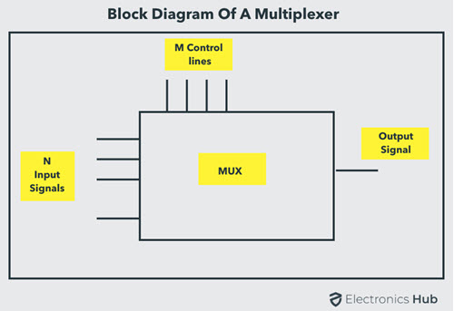
The multiplexer used for digital applications, also called digital multiplexer, is a circuit with many input but only one output. By applying control signals (also known as Select Signals), we can steer any input to the output. Some of the common types of multiplexer are 2-to-1, 4-to-1, 8-to-1, 16-to-1 multiplexer.
Following figure shows the general idea of a multiplexer with n input signal, m control signals and one output signal.
Understanding 4-to-1 Multiplexer
The 4-to-1 multiplexer has 4 input bits, 2 control or select bits, and 1 output bit. The four input bits are D0,D1,D2 and D3. Only one of this is transmitted to the output Y. The output depends on the values of A and B, which are the control inputs. The control input determines which of the input data bit is transmitted to the output.
For instance, as shown in figure, when A B = 0 0 , the upper AND gate is enabled, while all other AND gates are disabled. Therefore, data bit D0 is transmitted to the output, giving Y = Do.
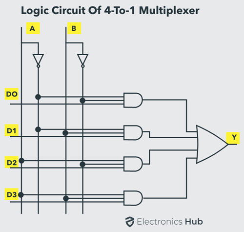
If the control input is changed to A B = 1 1 , all gates are disabled except the bottom AND gate. In this case, D3 is transmitted to the output and Y = D3.
- An example of 4-to-1 multiplexer is IC 74153 in which the output is same as the input.
- Another example of 4-to-1 multiplexer is 45352 in which the output is the compliment of the input.
- Example of 16-to-1 line multiplexer is IC 74150.
Applications of Multiplexer
Multiplexer are used in various fields where multiple data need to be transmitted using a single line. Following are some of the applications of multiplexers –
- Communication System – Communication system is a set of system that enable communication like transmission system, relay and tributary station, and communication network. The efficiency of communication system can be increased considerably using multiplexer. Multiplexer allow the process of transmitting different type of data such as audio, video at the same time using a single transmission line.
- Telephone Network – In telephone network, multiple audio signals are integrated on a single line for transmission with the help of multiplexers. In this way, multiple audio signals can be isolated and eventually, the desire audio signals reach the intended recipients.
- Computer Memory – Multiplexers are used to implement huge amount of memory into the computer, at the same time reduces the number of copper lines required to connect the memory to other parts of the computer circuit.
- Transmission from the Computer System of a Satellite – Multiplexer can be used for the transmission of data signals from the computer system of a satellite or spacecraft to the ground system using the GPS (Global Positioning System) satellites.
This is just an introduction to the concept of Multiplexer. To learn more about Multiplexers, read this Multiplexer (MUX) and Multiplexing tutorial.
Explain Working Of Demultiplexer
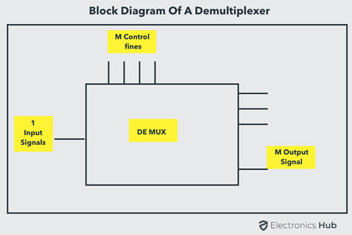
Demultiplexer means one to many. A demultiplexer is a circuit with one input and many outputs. By applying control signal, we can steer any input to the output. Few types of demultiplexer are 1-to 2, 1-to-4, 1-to-8 and 1-to 16 demultiplexer.
Following figure illustrate the general idea of a demultiplexer with 1 input signal, m control signals, and n output signals.
Understanding 1-to-4 Demultiplexer
The 1-to-4 demultiplexer has 1 input bit, 2 control or select bits, and 4 output bits. An example of 1-to-4 demultiplexer is IC 74155. The 1-to-4 demultiplexer is shown in figure below-
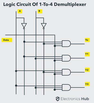
The input bit is labelled as Data D. This data bit is transmitted to the selected output lines, which depends on the values of A and B, the control or Select Inputs.
When A B = 0 1 , the second AND gate from the top is enabled while other AND gates are disabled. Therefore, data bit D is transmitted to the output Y1, giving Y1 = Data.
If D is LOW, Y1 is LOW. If D is HIGH, Y1 is HIGH. The value of Y1 depends upon the value of D. All other outputs are in low state.
If the control input is changed to A B = 1 0 , all the gates are disabled except the third AND gate from the top. Then, D is transmitted only to the Y2 output, and Y2 = Data.
Example of 1-to-16 demultiplexer is IC 74154. It has 1 input bit, 4 control / select bits and 16 output bit.
Applications of Demultiplexer
- Demultiplexer is used to connect a single source to multiple destinations. The main application area of demultiplexer is communication system, where multiplexers are used. Most of the communication system are bidirectional i.e., they function in both ways (transmitting and receiving signals). Hence, for most of the applications, the multiplexer and demultiplexer work in sync. Demultiplexer are also used for reconstruction of parallel data and ALU circuits.
- Communication System – Communication system use multiplexer to carry multiple data like audio, video and other form of data using a single line for transmission. This process make the transmission easier. The demultiplexer receive the output signals of the multiplexer and converts them back to the original form of the data at the receiving end. The multiplexer and demultiplexer work together to carry out the process of transmission and reception of data in communication system.
- ALU (Arithmetic Logic Unit) – In an ALU circuit, the output of ALU can be stored in multiple registers or storage units with the help of demultiplexer. The output of ALU is fed as the data input to the demultiplexer. Each output of demultiplexer is connected to multiple register which can be stored in the registers.
- Serial to Parallel Converter – A serial to parallel converter is used for reconstructing parallel data from incoming serial data stream. In this technique, serial data from the incoming serial data stream is given as data input to the demultiplexer at the regular intervals. A counter is attach to the control input of the demultiplexer. This counter directs the data signal to the output of the demultiplexer where these data signals are stored. When all data signals have been stored, the output of the demultiplexer can be retrieved and read out in parallel.
This is just an introduction to the concept of Demultiplexer. To learn more about Demultiplexers, read this What is Demultiplexer (DEMUX) tutorial.
Multiplexer vs. Demultiplexer: Key Differences
1. Input and Output
Multiplexers have multiple input lines, each carrying a potential data signal. These input lines are selected by control signals, often referred to as select lines. The chosen input is then transmitted to a single output line. In contrast, Demultiplexers operate in reverse. They have a single input line and multiple output lines. The input data is directed to a specific output line based on the control signals, effectively distributing the data across multiple channels.
2. Data Flow
A Multiplexer exhibits a many-to-one data flow, consolidating multiple input data streams into a single output channel. This consolidation is achieved through the selection process governed by the control signals. And, Demultiplexer operates in the opposite direction, characterized by a one-to-many data flow. It distributes a single input signal across multiple output lines, with the specific output channel determined by the control signals.
3. Function
Multiplexer acts as a data selector. It chooses one input signal from multiple inputs based on the control signals applied to its select lines. Essentially, it combines several data streams into a single output. While, a Demultiplexer performs the opposite function. It takes a single input signal and distributes it to multiple output lines, selecting the specific output channel based on the control signals. In essence, it acts as a data distributor.
Conclusion
An introductory tutorial on Multiplexer and Demultiplexer. Learn the basics of Multiplexer, understand a basic 4-to-1 Multiplexer, applications of Multiplexer, Demultiplexer, a basic 1-to-4 Demultiplexer, applications of Demultiplexer.

40 Responses
Thanks a lot it’s very useful to me
Thanks
Thanks so much. That was very helpful.
thank you bro that is very helpful information.
Thnx ….
This is very helpful for me..
Great information bro..
Hi..can u please tell me the dfference between multiplexer and multiplier?
It is helpful
very helpful
thanks for the information.
good and simple answer
so thanks its very useful to me
Thank you very much.
BEST WISHES
important message very helpful
Thanks it save me. Reading to pass my exams
Thanks mehn. It really helped. Reading for a test.
Thanks…very helpful
its so much important…thanks
its really valluable info to the communication students . tqqq very much
Hi thanks for the information, its very helpful. Can you tell me how the deultiplexer connects the recieved signal to the correct reciever. I know it is synchronised but what method is used. Is it the binary code that the demultiplexer reads?
Regards
Peter
Very nice article
That is very important for electronics students.
Thanks
i have a question
show how two 3-to-1 block diagram multiplexers (without enable inputs) are connected to form a 5-to-1 multiplexer. use no added gates. input selection should be as follows : if DC=00 then :AB selects I1/I2/I3 , if DC=01 selects I4 and if DC=10 selects I5 . give the function table of this 5-to-1 multiplexer and its connection diagram
thanks a lot you are a good teacher
So useful in students & latucher s
this is helpful
superb thanku
Hi great explanation.I never knew about this
Thank you sir
It is very useful to me
To refer about this topic
very useful for me
Very helpful…. And given in very easy language
Hi… thanks…. very useful information.
Is there 2×4 de multiplexer..
Is it like 1×2 de multiplexer???
Awesome it’s very useful for me to?
Design a MUX-DEMUX with registered outputs 4 to 1 mux and followed by 1 to 8 demux and using flipflops for demux output?
Thanks…..!
for great help
Thank you. It’s also very useful for me!!
This is a good explanation. It really helped me understand.
thank you..very helpful
Great !!! Very Helpful…
It is very helpful..thank you