Conventional methods of audio amplification use high power circuits to drive a loudspeaker for areas like an auditorium or any other hall. However for applications involving use of small loudspeakers for low range requirements, we can meet the requirements by constructing a low power amplifier with a low output current such as 200 mA.
In this article we are describing the principle, design and operation of a low power audio amplifier using 555 Timer. The 555 Timer generates a carrier signal which is modulated by the amplified audio signal to produce a modulated signal. This signal is used to drive a small loudspeaker.
Low Power Audio Amplifier Circuit Principle:
Here this circuit is based on the principle of audio amplification using operational amplifier and pulse width modulation using 555 Timer. The audio signal is amplified using low noise high input operational amplifier TL071 and is fed to the control pin of the 555 Timer. 555 Timer is used as an astable multivibrator producing an oscillating signal. This signal is modulated by the audio signal such that the width of the output pulse varies with respect to the voltage at the control pin (the audio signal), causing pulse width modulation.
555 Timer as an Amplifier Circuit Diagram:
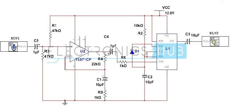
- Circuit Diagram of a Low Power Audio Amplifier using 555 Timer – Electronics Hub
Circuit Design of Low Power Audio Amplifier:
Here the circuit designing is a simple process involving just two steps – designing the preamplifier section and designing the astable multivibrator section.
Here we are using a low noise JFET input operational amplifier TL071 with low input bias current and high slew rate of about 13V/µs. A voltage divider network is designed using two resistors each of 47K, so that a voltage of 6V is applied to the non inverting terminal of the OPAMP. Assuming our required gain to be around 22(V/V) or 27.2dB and the value of one of the feedback resistors to be around 1K, we calculate the value of another resistor to be around 22K. Since output impedance is low for this amplifier, we use a resistor of about 1K at the output to connect it to the control pin of the 555 Timer.
Next step in the design process involves designing the 555 timer astable circuit. In normal circuit connection for 555 Timer as astable multivibrator, we use two resistors for both charging and discharging of the capacitor. However to provide faster discharge rate, we use here a diode 1N4007 instead of the resistor. Here our required output frequency is around 145 KHz and assuming the value of capacitor to be around 10nF, we can calculate the value of threshold resistor to be around 1K (Forward resistance of 1N4007 is around 1Ohms).
Related Post – 100w Subwoofer Amplifier Circuit
Low Power Audio Amplifier using 555 Timer Circuit Simulation:
Once the circuit is designed, the next step involves timer circuit simulation. Here we follow a series of steps to simulate the circuit using Multisim software.
- The microphone simulation model is selected from the LabView instruments under Simulate menu.
- Required parameters are set accordingly (The time of recording and sampling rate).
- The designed circuit is build using the software and the microphone is connected as input to the circuit.
- A loudspeaker model is selected from the LabView instruments under Simulate menu and connected as output to the circuit
- The interactive simulation setting is accomplished by setting the end time equal to or more than the time of recording.
- As long as the circuit simulation takes place, the ‘Play’ button of the loudspeaker is grayed out and once the simulation ends, the button is enabled.
How 555 Timer as an Amplifier Circuit Works?
The circuit operation is divided into two segments – the pre amplifying (electric signal amplification) operation and the pulse width modulation operation. The amplifying operation is performed by the low noise operational amplifier TL071. The input audio signal is sensed using the microphone and converted to a low voltage electric signal. This low voltage AC signal is fed to the non inverting terminal of the OPAMP through an electrolyte capacitor of 1uF, which blocks the DC current of the audio signal.
This signal is amplified using the operational amplifier with a gain depending upon the values of feedback resistors. Here the OPAMP works in linear mode so as to make the voltage at non inverting terminal equal to the output voltage using the feedback network. This amplified signal is then fed to the control pin of the 555 Timer through the capacitor (to remove the DC component) and the resistor. Here the 555 Timer works in the astable mode with the frequency of output signal determined by the combination of resistors R1 and C1.
However since here we are applying the control voltage, the width of the output pulse varies depending upon the control voltage. The carrier output signal produced by the 555 Timer is modulated by the audio voltage and the resultant modulated signal is used to the drive the loudspeaker. Here the loudspeaker does not responds to the high frequency signal, but rather to the DC value of the modulated signal and thus the audio signal appears amplified.
555 Timer as an Amplifier Circuit Applications:
- This application can be used to develop low power music systems used in vehicles.
- It can be used in classrooms with limited areas.
Limitations of Audio Amplifier Circuit:
- This circuit is suitable only for low power loudspeakers.
- 555 Timer doesn’t produce 50% duty cycle signal.
- This circuit is theoretical and may require changes in hardware implementation.
