Have you ever made your own robot? Here is a very simple and easy robot. In this project, I will explain how to design and build a Line Follower Robot using microcontroller. The Line Follower Robot is a basic robot that follows a specific path indicated by a line (usually a black line on a light colored surface) having some particular width.
Line Follower Robot Circuit Principle
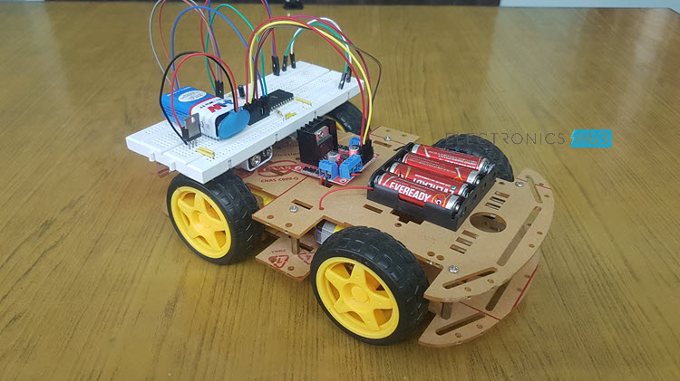
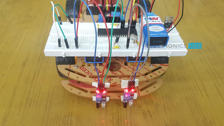
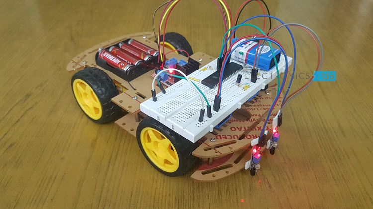
This circuit mainly consists of 8051 microcontroller, two IR sensors, motors and motor driver IC (embedded in a module). The line follower robot needs mechanical arrangement of the chassis. I have used a 4WD Acrylic chassis. The two IR sensors are mounted on the fron of the robot facing with the diodes facing towards Earth.
When robot is placed on the fixed path, it follows the path by detecting the line. The robot direction of motion depends on the two sensors outputs. When the two sensors are on the line of path, robot moves forward. If the left sensor moves away from the line, robot moves towards right. Similarly, if right sensor moves away from the path, robot moves towards its left. Whenever robot moves away from its path it is detected by the IR sensor.
Do you know about How Remote Controlled Spy Robot Circuit Works?
IR sensor consists of IR transmitter and IR receiver on a board. When the vehicle is moving on a black line, IR rays are continuously absorbed by the black surface and there is no reflected ray making output high. Whenever, the robot moves out to the white surface, it starts reflecting the IR rays and making the output low. Thus depending on the output of IR sensor microcontroller indicates the motors to change their direction.
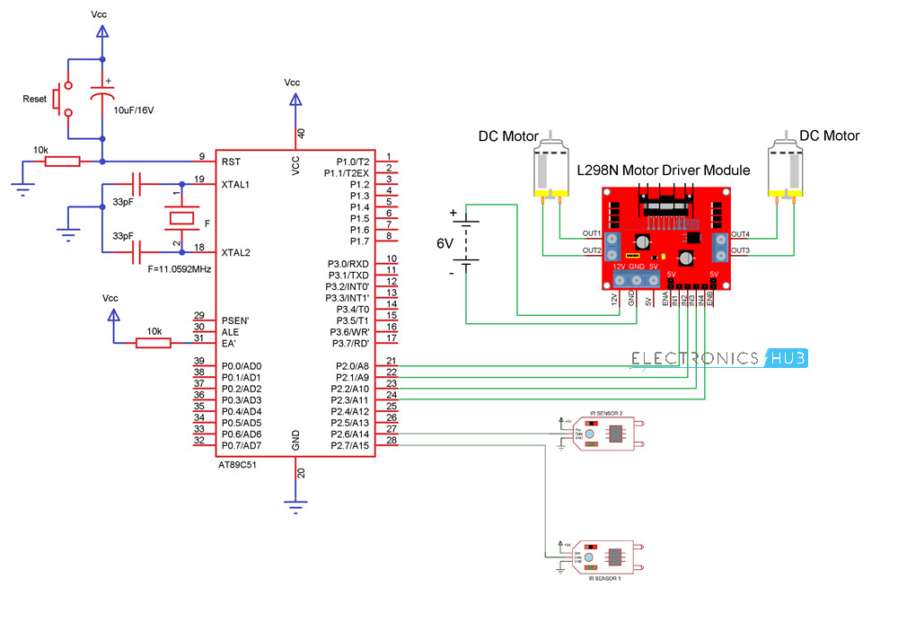
Line Follower Robot Circuit Diagram
Components in the circuit
- 8051 Microcontroller
- Development Board for 8051 Microcontroller (preferred)
- 10KΩ Resistors X 2
- 10µF Capacitor
- 11.0592MHz Crystal
- 33pF Capacitors X 2
- Push Button
- Motor driver Module (L298N)
- Robot Chassis with Motors
- IR Sensors x 2
How to Design a Line Following Robot?
The circuit consists of 8051 microcontroller, IR Sensors (with IR transmitter and IR Receiver), L298N Motor Driver Module, Robot Chassis with 4 wheels and 4 motors, battery holder.
8051 microcontroller is the main component of the project. It is an 8 bit microcontroller with 32 programmable I/O pins. This has many peripheral features like programmable UART, two 8-bit timer/counter, two interrupts, external memory access etc.
The DC motors of the robot are connected to the controller using a motor driver IC. As the output of the controller is maximum 5V with very small current, it cannot drive the motors. So, to amplify this voltage motor driver IC is used. L298N can drive motors up to 36v and can provide a drive current of 3A.
The driver IC has 15 pins and is usually available in multiwatt15 Package. These ICs are easily available in the market as Modules. The inputs to the Motor Driver Module are connected to PORT2 pins P2.0, P2.1, P2.2 and P2.3.
The two IR sensors are connected to P2.6 and P2.7 pins of the microcontroller. Arrange the chassis and connect the four wheels of the robotic vehicle to the motors which are in turn connected to the microcontroller.
Related Post: DTMF Controlled Robotic Vehicle without using Microcontroller
Design of IR Sensors
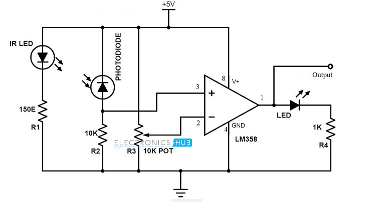
IR sensor circuit consists of mainly IR transmitter and IR receiver. IR transmitter is similar to an LED. Its operating voltage is around 1.4V. So to protect it, a 150Ω resistor is placed in series with it and is connected in forward biased. IR receiver is connected in reverse bias and a 10KΩ resistor is placed between VCC and the receiver. Output is taken between resistor and IR receiver.
Since this is an analog output, we can convert it to a digital HIGH and LOW with the help of a simple comparator IC like LM358, for example. The IR Sensor Module used in this project uses the same configuration and the circuit diagram is shown below.
Working of IR Sensors
The IR transmitter continuously transmits the IR rays. When IR transmitter is on the black surface these rays were absorbed by the surface and when it is on white surface these rays were reflected. The IR receiver has maximum resistance when no IR rays are received and voltage from VCC flows through the resistor. At the output pin, voltage is approximately 5V.
As the intensity IR rays received by the receiver increases, resistance value decreases and reverse break down occurs. Thus voltage through the resistor is grounded. So, at the output pin, it will produce 0V.
Line Following Robotic Vehicle Circuit Working
- Initially draw the path on a light colored surface with black color tape.
- Place the robot on the floor.
- Now power on the circuit.
- Robot moves in the specified path.
- When it moves out of path, sensors check it and automatically adjust the robot.
Code
Line Following Robot Circuit Applications
- This can be used in driver less car system with some added features like obstacle detection.
- This can also be used in industrial and defense applications.
Limitations of Line Follower Robot
- Line follower robot requires 2-3 inches broad line.
- It may not move properly if the black line drawn is of low intensity.
- The IR sensors may sometimes absorb IR rays from surroundings also. As a result, robots may move in improper way.
Note: If anybody interested on more robotics projects, visit the page: Robotics Projects

14 Responses
Need a Preset of 5K or 10K in place of R3 and R4 because all IR rx will not generate perfect output and even that output should be calibrated depends on the reflective surface at the real time..
Lol.. how IR tx will generate a IR light if u use 10K resistor
sol: go with range between 220 ohms to 1k ohm.. in place of R1 and R3…
L293d is not going to amplify any voltage.. it just acts as a control unit for forward and reverse flow of current for motors either to rotate it in backward or forward direction.. but it can with stand up to voltage of 36v without any problem and max current is 600 milli-amps for each motor.. recommended ratings is 400- 450 milli-amps and even 12-18 volts
SUggetion: Adimins pls go with some corrections atleast in some basics.. So many people are simply following u… ultimatly they may fail in result
plz send me the component list to make lfr using atmega 8 with obstacle detector
You can make both line follower and obstacle detector robots using the above mentioned components. While doing the obstacle detector robot change code and IR sensors position
sir i wants to make a line following robot with multisensores for increasing the speed with accuracy. So how its made ?
sir, give me the proper circuit diagram to make an IR circuit for object detection plzz
plz send me the component list to make lfr using atmega 8 with obstacle detector
arduino keil 8051
i need circuit for metal detector plz
can you provide fritzing circuit diagram
hey how to get the development board and ir module
sir, can i get your project code?
pls mail me the list of components
Required components we have mentioned on the same page.
is it possible with a Grove – Line finder v1.1.?