Light Emitting Diode or simply LED is one of the most commonly used sources of light now-a-days. Whether it may be your car’s headlights (or daytime running lights) or your home’s living room lights, the applications of LEDs are countless.
Unlike (almost) legacy filament bulbs, LEDs (and fluorescent bulbs) need a special circuit to make them work. They are simply called as LED Drivers (or a ballast in case of fluorescent bulbs).
Since LEDs are inevitable in our lives, it is a good idea for the interested folks (engineers, driver designers etc.) to get to know the Light Emitting Diode Basics. This article is composed as a brief understanding guide to LED, which includes a brief introduction, the electrical symbol of LED, types, construction, characteristics, LED Drivers and many.
NOTE: There is a simpler version of this article “LED – Light Emitting Diode“, which gives an overview of an LED in a more simpler manner without going into the technical details.
Light Emitting Diode
The two most significant semiconductor light emitting sources extensively used in various applications are LASER diodes and LED’s. The principle operation of LASER diodes is based on stimulated emission, whereas LED is based on spontaneous emission.
Light Emitting Diodes are the most common eminent source of light available in electronic components. For instance, they are widely used for displaying the time and many other types of data on screens in certain display devices. LEDs are the opto-semiconductor devices, which easily converts electric current into illumination (or light). Area of the LED is usually very less and many integrated optical components may be used in designing its radiation pattern. It has the major advantage of low manufacturing cost and renders longer life than the laser diode.
A light emitting diode consists of two principal elements of semiconductor. They are positively charged P-type holes and negatively charged N-type electrons.
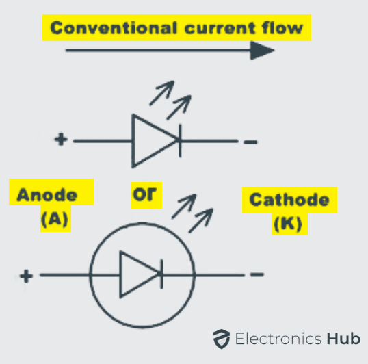
When the positive P side of the diode is connected to power supply and N side to the ground, then the connection is said to be in forward bias, which allows the electric current to flow through the diode. The majority and minority charge carriers of P side and N side combine with each other and neutralize the charge carriers in the depletion layer at the PN junction.
The migration of electrons and holes in turn releases some amount of photons, which discharges energy in the form of monochromatic light at a constant wavelength usually in nm, which resembles the color of an LED. The color spectrum of LED emission is typically extremely narrow.
In general, it can be specified as a certain specific range of wavelengths in the electromagnetic spectrum. The selection of emission of color from the LED is fairly limited due to the nature of semiconductor used in the manufacture. Commonly available colors of LED are red, green, blue, yellow, amber and white.
The light from red, blue and green colors can be easily combined to produce white light with limited brightness. The working voltage of red, green, amber and yellow colors is around 1.8 volts. The actual range of working voltage of a light emitting diode can be determined by the breakdown voltage of semiconductor material involve in the construction of LED. The color of the light emitted in LED is determined by the semiconductor materials that form the diode’s PN junction.
It is due to the differences in the energy gap band structure of semiconductor materials and so different number of photons is emitted with varying frequencies. However the wavelength of light depends on the band gap of the semiconductor materials at the junction and the intensity of light depends on the amount of power or energy applied through the diode. The output wavelength can be maintained by using compound semiconductors, so that required color can be observed, providing the output within the visible range.
Light can be produced and controlled by electronic means in a number of ways. In light emitting diodes, light is produced through the concept of electroluminescence which is a solid state process. Under certain specific conditions of producing the light, solid state procedures can produce a coherent light, similarly as in laser diodes.
Types of LEDs
Light emitting diodes can be broadly classified as two major categories of LEDs. They are
- Visible LEDs
- Invisible LEDs
Visible LEDs are primarily used for switches, optical displays and for illumination purposes without the use of any photo sensors. Invisible LEDs are used in applications including optical switches, analysis and optical communications, etc., with the use of photo sensors.
Efficacy
The rating of light emitting diodes is determined in terms of its luminous efficacy. It is defined as the ratio of luminous flux to the electrical input power supplied to the diode and it can be expressed in lumens per watts. Luminous flux represents the response of the eye to different wavelengths of light.
LED Construction
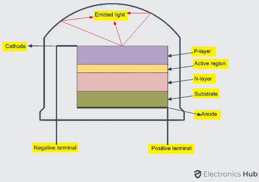
The structure and construction of Light Emitting Diodes are much different from that of a regular semiconductor signal diode. Light will be emitted from the LED when its PN junction is forward biased. The PN junction is covered by a transparent solid and plastic epoxy resin hemispherical shaped shell body which protects the LED from atmospheric disturbances, vibrations and thermal shock. The PN junction is formed using the lowest band gap materials like Gallium Arsenide, Gallium Arsenide Phosphide, Gallium Phosphide, Gallium Indium Nitride, Aluminum Gallium Nitride, Silicon Carbide etc.
Actually an LED junction does not emit much amount of light so that the epoxy resin body is built in such a way that the photons of light emitted by the junction are reflected away from the surrounding substrate base and are focused through the domed top of the LED, which itself acts as a lens concentrating the larger amount of light.
It is the reason why the emitted light appears to be brightest at the top of LED.
Usually, Light Emitting Diodes which emits red colored light are built on Gallium Arsenide substrate and the diodes which emit green/yellow/orange colored lights are fictitious on the Gallium Phosphide substrate. For red color emission, the N – type layer is doped with Tellurium (Te) and the P – type layer is doped with Zinc. Contact layers are formed using Aluminum on P – side and Aluminum Tin on N – side respectively.
The LEDs are designed to make sure that the most of the recombination of charge carriers takes place on the surface of the PN junction by the following ways.
- By increasing the substrate doping concentration, the additional minority charge carriers electrons move to the top of the structure, recombine and emit light at the surface of LED.
- By increasing the diffusion length of charge carriers, i.e., L = √ Dτ, where D is the coefficient of diffusion and τ is the charge carrier life time. When increased beyond the critical value there will be a chance of re-absorption of the released photons into the device.
When the diode is connected in forward bias, the charge carriers acquire sufficient amount of energy to surmount the barrier potential existing at the PN junction. Whenever the forward bias is applied, the minority charge carriers on both P – type and N – type are injected across the junction and recombine with the majority carriers. This recombination of majority and minority charge carriers may be either radiative or nonradiative. Radiative recombination emits light and Nonradiative recombination produce heat.
Organic Light Emitting Diodes (OLED)
In organic Light Emitting Diodes the compound semiconductor material used in designing the LED is organic in nature. The organic semiconductor material is electrically conductive in some part or the entire molecule due to the conjugated electron; as a result it is an organic semiconductor. The material may be in crystalline phase or polymeric molecules. It has the advantage of thin structure, less cost, low voltage for driving, excellent radiation pattern, high radiance, maximum contrast and intensity.
Light Emitting Diode Colors
In contrast to the normal semiconductor, signal diodes that are used for switching circuits, rectifiers and power electronics circuits made from either silicon or germanium semiconductor materials, the Light Emitting Diodes are manufactured from compound semiconductor materials such as Gallium Arsenide, Gallium Arsenide Phosphide, Silicon Carbide and Gallium Indium Nitride are all mixed together in different ratios to produce a unique distinctive wavelength of color.
Different semiconductor compounds emit light in definite regions of the visible light spectrum and therefore they produce different intensity levels of light. The choice of the semiconductor material used in manufacturing the LED will determine the wavelength of the photon emissions and the resulting color of the emitted light.
Radiation Pattern
It is defined as the angle of the light emission with respect to the emitting surface. The maximum amount of power, intensity or energy will be obtained in the perpendicular direction with the surface emitting. The angle of light emission depends on the color being emitted and it usually varies between around 80° to 110°.
| Gallium Arsenide | |||
| Aluminium Gallium Arsenide | |||
| Aluminium Gallium Arsenide | |||
| Gallium Arsenide Phosphide | |||
| Aluminium Gallium Indium Phosphide | |||
| Gallium Phosphide | |||
| Gallium Arsenide Phosphide | |||
| Aluminium Gallium Indium Phosphide | |||
| Gallium Phosphide | |||
| Gallium Arsenide Phosphide | |||
| Aluminium Gallium Indium Phosphide | |||
| Gallium Phosphide | |||
| Gallium Indium Phosphide | |||
| Aluminium Gallium Indium Phosphide | |||
| Aluminium Gallium Phosphide | |||
| Indium Gallium Nitride | |||
| Zinc Selenide | |||
| Indium Gallium Nitride | |||
| Silicon Carbide | |||
| Silicon | |||
| Indium gallium Nitride | |||
| Dual Blue/Red LEDs | |||
| Blue with Red Phosphor | |||
| White with Purple Plastic | |||
| Diamond | |||
| Boron Nitride | |||
| Aluminium Nitride | |||
| Aluminium Gallium Nitride | |||
| Aluminium gallium Indium Nitride | |||
| Blue with phosphor | |||
| Yellow with Red, Orange or Pink phospor | |||
| White with Pink pigment | |||
| Blue/UV diode with Yellow Phosphor |
The color of the light emitted by an LED is not determined by the color of the plastic body enclosing the LED. The enclosing is used to both enhance the light emission and to indicate its color when it’s not driven by an electrical supply. In the recent years, blue and white LEDs are also available, but these are more expensive than the normal standard color LEDs due to the production costs of mixing two or more complementary colors in an exact ratio within the semiconductor compound.
General Characteristics of Light Sources
Drive Current Vs Light Output
For high values of forward drive current the temperature of the PN junction of semiconductor increases due to considerable power dissipation. This type of rise in temperature at the junction results in decrease in the efficiency of radiative recombination. As a result, the density of current is further increased; internal series resistance will tend to reduce the light emitting efficiency of any light source.
Quantum Efficiency
The Quantum efficiency of any light source is defined as the ratio of the radiative recombination rate, which emits light to total recombination rate and it is given as:
η=Rr/Rt
Switching Speed
The switching speed of a light source resembles how fast a light source can turn on and off by an applied electrical supply to produce a corresponding pattern of optical output. LEDs have slow switching speed than usual LASER diodes.
Spectral Wavelength
The peak spectral wavelength is defined as the wavelength at which the maximum intensity of light is generated. It is determined by the energy band gap of the semiconductor material used in LED manufacturing.
Spectral Width
The spectral width of a light source is defined as the range of wavelengths over which a light source emits light. The light source has to emit light within the narrower spectral width.
LED I-V Characteristics
Before emitting light from any light emitting diode, it needs to have current to flow across it, since LED is a current dependent device with its output light intensity being directly proportional to the forward current passing through the LED.
Light emitting diode has to be connected in a forward bias combination across the power supply and it should be current limited by using a resistor connected in series to protect it from the excess current flow. LED should not be connected directly to the battery or power supply because excess amounts of current will flow through it and LED may damage.
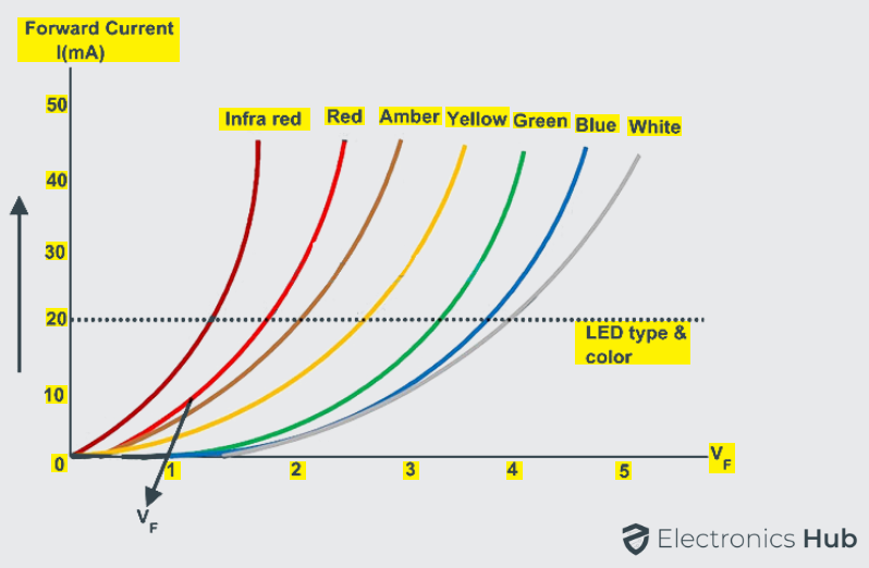
Each LED has its own individual forward voltage drop along the PN junction and this parameter has been determined by the semiconductor material used in manufacturing of LED for a specified amount of forward conduction current, usually for a forward current of about 20mA.
At low forward voltages, the driving current of the diode is dominated by the non-radiative recombination current due to recombination of charge carriers across the length of the LED chip. At higher forward voltages, the diode driving current is dominated by the radiative diffusion current.
Even at larger voltages than the usual, the diode current is limited by the series resistance. The diode should never reach to reverse breakdown voltage for a short duration of time since permanent damage of the diode may occur. The below figure shows the I-V characteristics of the different color LEDs.
LED Series Resistance Calculation
Light emitting diode functions well when it is connected in series with the resistance, as a result the forward current required by the LED is provided by supply voltage across the combination. The resistance value of the series resistor can be calculated using the below formula. Usually the forward current of a normal LED is considered as 20mA.

Multi – Color Light Emitting Diode
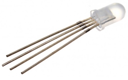
There are large numbers of LEDs available in the market with varying shapes and sizes, different colors and different light output intensities. Gallium Arsenide Phosphide red colored Led with the diameter of 5 mm is the most commonly used LED and it is very cheap to produce. Light emitting diodes with multiple color emission are being manufactured nowadays and they are available in many packages, most of them are two to three LEDs within a single package.
Bi-Color Light Emitting Diodes
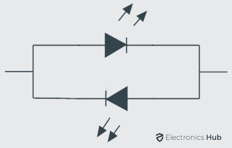
The bi-color light emitting diodes are a type of LEDs similar to single color LEDs just with additional one more LED chip enclosed in the package. The bi-color LEDs may have either two or three leads for connecting; it depends on the method used. In general the two LED leads are connected in inverse parallel combination. The anode of one LED is connected to the cathode of another LED and vice versa. When the supply is given to either of the anode only one LED will glow. We can also turn on both LEDs at same time with dynamic switching at high speed.
Tri Colored Light Emitting Diode
Usually three lead LED have common cathode lead in which both the other two LED chips are connected internally. Either one or two LEDs have to be turned on, it is necessary to connect the common cathode to ground. The current limiting resistors are connected to the both anodes for controlling the current individually.
For single or bi-color LED illumination it is necessary to connect power supply to either of the anodes individually or at the same time. These tricolored LEDs comprises of single RED and GREEN LED chips connected to the same cathode. This type of diodes generates additional shades of the primary colors by switching ON the two LEDs in different ratios of forward current.
LED Driver Circuits
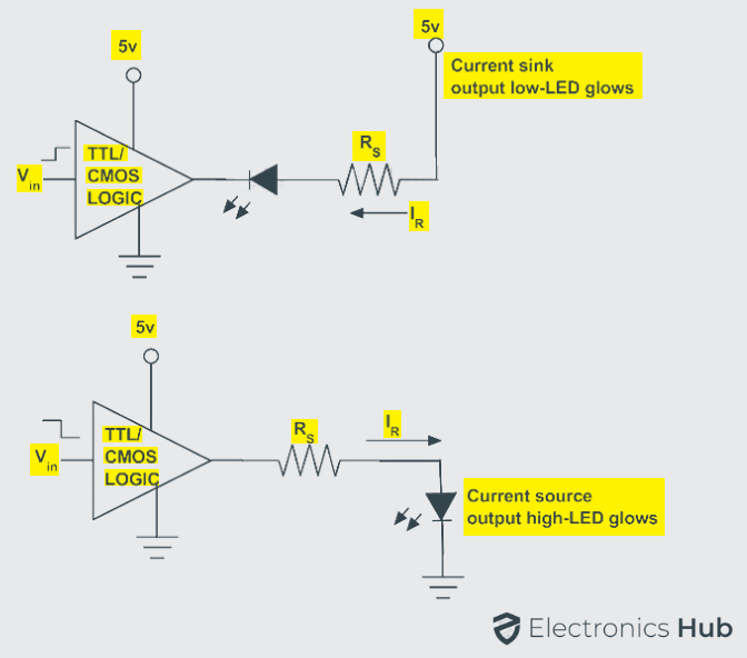
Integrated circuits either the combinational circuits or sequential circuits can be used to drive the light emitting diodes. The light emitting diodes can be switched on or off using integrated circuits. The output stages of TTL or CMOS logic gates can be used to drive the light emitting diodes as switches in two modes of configuration. They are source and sink modes of configuration.
The output current given by integrated circuits in sink mode configuration can be about 50 mA and in source mode configuration the forward current can be about 30 mA. However the current driven by the light emitting diode should be limited by the resistor connected in series.
Driving an LED Using Transistor
Instead of using Integrated circuits, the LEDs can be driven by using discrete components such as bipolar PNP and NPN transistors. The discrete components can be used in driving more than one LED as in large LED array structures.
Fewer applications use solely a single LED in their functioning. Junction transistors are used to drive current across the multiple light emitting diodes in such a way that the forward current driven by LED is about 10 – 20 mA. If NPN transistor is used in driving the LED then the series resistor acts as a current source. If PNP transistor is used in driving LEDs then the series resistor acts as a current sink.

Applications such as backlighting array of screen, street lights or as a replacement for fluorescent lamp or incandescent lamp, most of the applications require more than one LED. Generally, driving a number of single LEDs in parallel causes non uniform current sharing among the LEDs; even then all the LEDs are rated for the same forward voltage drop.
If single LED fails in driving the LEDs in series can be overcome by providing parallel Zener diodes or silicon controlled rectifiers (SCRs) across each single LED in series. SCRs are the smart choice because they dissipate less power if they have to carry out around the failed LED.
In the case of a parallel combination including a separate driver for each string is more expensive than using a few drivers with appropriate output capacity.
Controlling of LED Light Intensity using PWM
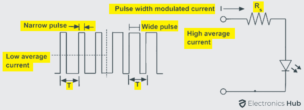
The intensity of light emitted by the LED is controlled by the current flowing through it. As the current across it varies, the brightness of the light can be controlled. If a large amount of current is allowed to pass through the diode, LED light glows much better than the usual.
If the current exceeds its maximum value, the intensity of light increases further and cause the LED to dissipate heat. The forward current limit set for designing LED ranging about 10 to 40 mA. When the current required is very less there may be chances of turning off the LED.
In such cases to control the brightness of light and the current required by LED, a process known as pulse width modulation is used for repeatedly turning the LED ON and OFF depending on the intensity of light required. Linear control devices dissipate the excess energy in the form of heat, as a result to deliver the required amount of power, PWM drivers are used because they do not deliver the power at all.
First of all to inject PWM pulses to the LED circuits, a PWM oscillator is first required. There are different numbers of PWM generators.
LED Displays
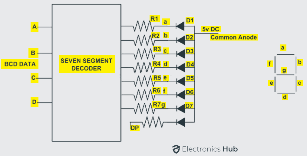
Single color, bicolor, multicolor and several other Light emitting diodes are combined as a single package. They can be used as back lightening, strips and bar graphs. One essential requirement of digital display devices is visual numeric display. The common example of such single package of several LEDs is seen in seven segment displays.
A seven segment display, as the name suggests it consists of seven LEDs within the single display package. It can be used for displaying the information.
The display information may be in the digital data form of numbers, letters, characters and also alphanumeric characters. The seven segment display usually has eight combinations of input connections, one for each LED and the remaining one is a common connection point for all the internal LEDs.
If the cathodes of all the LEDs are connected together and by applying a logic HIGH signal, then the individual segments are illuminated. In the same manner if anodes of all the LEDs are connected together and by applying a logic LOW signal, then the individual segments are illuminated.
LED Advantages, Disadvantages and Applications
Advantages
- Small Chip size and low cost
- Long life time
- High energy efficiency
- Low temperature
- Flexibility in design
- Many colors
- Eco friendly
- High switching speed
- High luminous intensity
- Designed to focus its light in a particular direction
- Less affected by damages
- Less radiated heat
- More resistant to thermal shock and vibrations
- No presence of UV Rays
Disadvantages
- Ambient temperature dependence of radiant output power and wavelength of the LED.
- Sensitivity to damages by excess voltage and/or excess current.
- Theoretical overall efficiency is achieved only in special cool or pulsed conditions.
Applications
- In motor vehicles and bicycle lights
- In traffic light Indicators, signs and signals
- In data displaying boards
- In medical applications and toys
- Non visual applications
- In light bulbs and many more
- Remote controls

3 Responses
Wich type of led used in Not feeding detection sensor in pharmaceutical machines ???
Such a wonderful information , I really liked it , easily understood , very useful contents .
vry good info. keep it up