Capacitors are key electronic parts often overlooked but vital. They store and release electrical energy, crucial in many circuits. Knowing about capacitors is a must for electronics enthusiasts and tech learners. They do various jobs like smoothing power, filtering signals, and storing energy. Let’s uncover what makes capacitors important in today’s tech world.
What is Capacitor?
Capacitor is also known as condenser. This is one of the passive components like resistor. Capacitor is generally used to store the charge. In capacitor the charge is stored in the form of “electrical field”. Capacitors play a major role in many electrical and electronic circuits.
Generally, a capacitor has two parallel metal plates which are not connected to each other. The two plates in the capacitor are separated by non conducting medium (insulating medium) this medium is commonly known as Dielectric.
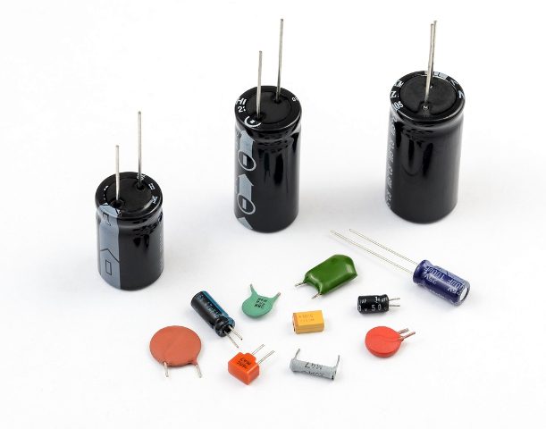
There are different types and different shapes of capacitors available , from very small capacitors which are used in resonance circuits to large capacitors for stabilising HVDC lines. But all capacitors are doing the same work that is storing the electrical charge.
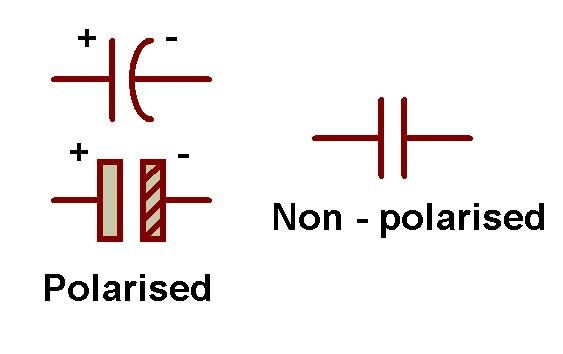
The shape of a capacitor is rectangular, square, circular, cylindrical or spherical shape. Unlike a resistor, an ideal capacitor does not dissipate energy. As the different types of capacitors are available different symbols were available to represent them which are shown below.
Why capacitors are important?
Capacitors have many properties like
- They can store the energy and it can dissipate this energy to the circuit when ever required.
- They can block DC and allow AC to flow through it, and this can couple one part of the circuit with the other.
- Circuits with capacitors depend on the frequency, so can be used to amplify certain frequencies.
- As the capacitors when applied with AC input , the current leads the voltage and thus in power applications it increases the pay load power and makes it more economical.
- It allows high frequencies and so it can be used as a filters either to filter low frequencies or to collect high frequencies.
- As the reactance and frequency of the capacitor are inversely related, this can be used to increase or decrease the circuit impedance at certain frequency and can be used as filter.
Likewise, capacitors exhibit many properties , when used in AC or DC circuits and hence they play important role in electrical and electronic circuits.
Construction of a Capacitor
As said before , there are different types of capacitors. These different types will have different type of construction. A Parallel plate capacitor is the simplest capacitor. Let us understand the construction of this capacitor.
It consists of two metal plate separated by a distance. The space between these two plates is filled with a dielectric material. The two leads of the capacitor are taken from these two plates.
The capacitance of the capacitor depends on the distance between the plates and area of the plates. Capacitance value can be changed by varying any of these parameters.
A variable capacitor can be constructed by making one of these plates fixed and other moving.
Dielectric Of a Capacitor
Dielectric acts as an insulating material between the plates . Dielectric can be any non conducting material such as ceramic, waxed paper, mica, plastic or some form of a liquid gel.
Dielectric also plays an important in deciding the value of capacitance. As the dielectric is introduced between the plates of the capacitor ,its value increases.
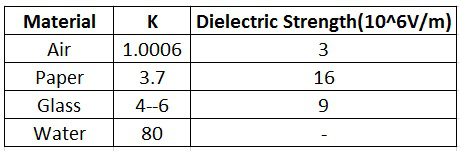
Different dielectric materials will have different dielectric constants ,however this value is >1.
Below table gives value of dielectric constant for each dielectric material
Dielectric can be of two types
- Polar dielectrics: These dielectrics will have permanent dielectric movement
- Non Polar dielectrics: These will have temporary dielectric moment. By placing them in a electric field they can be induced with dipole moments.
Complex Permittivity
The product of the relative permittivity (εr) of the dielectric material and permittivity of free space (εo) is known as “Complex permittivity” or “Actual permittivity” of the dielectric material. The expression for the complex permittivity is given as follows,
ε = ε0 * εr
The value of complex permittivity will always be equal to the relative permittivity, because the permittivity of free space is equal to ‘one’. The value of dielectric constant or complex permittivity varies from one dielectric material to another.
Some standard values of complex permittivity (ε) for common dielectric materials are Air = 1.0005, Pure Vacuum = 1.0000, Mica = 5 to 7, Paper = 2.5 to 3.5, Wood = 3 to 8, Glass = 3 to 10 and Metal Oxide Powders = 6 to 20 and etc.
capacitors can be classified according to the properties and characteristics of their insulating or dielectric material, they are given below as
- High Stability & Low Loss Capacitors — Mica, Low-K Ceramic, and Polystyrene capacitors are examples for this type.
- Medium Stability & Medium Loss Capacitors – Paper, Plastic Film, and High-K Ceramic capacitors are examples for this type.
- Polarized Capacitors – Example for this type of capacitors are Electrolytic, Tantalum’s.
Working
As said before capacitor consists of two conductor separated by a dielectric , when there is any potential difference between the two conductors electric potential is developed.This causes the capacitor to charge and discharge.
Let us understand this in a practical way. When the capacitor is connected to a battery(a DC source) , current starts flowing through the circuit .
Thus negative charge is accumulated on one plate and positive charge is accumulated on the other plate. This process continuous until the capacitor voltage reaches supply voltage.
When the charging voltage is equal to the supply voltage capacitor stops charging further even though the battery is connected. When the battery is removed two plates will be accumulated with positive and negative charges. Thus the charge is stored in the capacitor.
But when the supply voltage is from an AC source it charges and discharges continuously .The rate of charging and discharging depends on the frequency of the source.
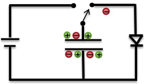
Example
Working can be understood using simple example here. Below circuit shows two switches A and B. When switch 1 is closed , current starts flowing from from the battery to the capacitor. When the capacitor voltage reaches the supply voltage ,it stops charging further.
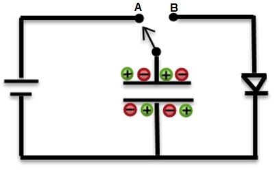
Now connect the switch to position B. Now you can observe the LED starts glowing and this slowly fades out as the capacitor is discharging.
Capacitance of the capacitor is given by
C=KεA/d
or
C= εA/4πd
or
C = εo * εr (A/d)
Where,
C – Capacitance of the capacitor
A – Area between the plates
D – Distance between the two Plates
εo – Permittivity of free space
εr – Relative permittivity.
K- Dielectric Constant
Capacitance of a Capacitor
Capacitance is the property of the capacitor that defines the maximum amount of electrical charge stored in it.it exists in nature everywhere.
Capacitance may vary depending on the shape of the capacitor. Capacitance can be calculated by using the geometry of the conductors and dielectric material properties. Let us see the capacitance of a parallel plate capacitor.
Capacitance is defined as the ratio of charge (Q) on the either plates to the potential difference(V) between them ,
C =Q/V,
Thus current can be obtained as
I(t)=C[d(v)/d(t)]
This can can be expressed Farads (F) which is named after English physicist Michael Faraday.
From the above definition we can observe that capacitance is directly proportional to the charge (Q) and is inversely proportional to the voltage (V).
Capacitance of the capacitor can be increased by increasing the number of plates, which helps to maintain the same size of the capacitor. Here, area of the plates is increased.
Standard units of capacitance
Generally Farads is a high value so, capacitance is expressed as sub units of capacitor real time such as as micro farads(uF) , nano farads(nF) and pico farads(PF).
Most of the electrical and electronic applications are covered by the following standard unit (SI) prefixes for easy calculations,
- 1 mF (milli farad) = 10−3 F = 1000 μF = 1000000 nF
- 1 μF (microfarad) =10−6 F = 1000 nF = 1000000 pF
- 1 nF (nano farad) = 10−9 F = 1000 pF
- 1 pF (picofarad) = 10−12 F
To convert µF to nF or pF or to a wide range of other units and vice versa, we need to use the Electric Capacitance Unit Converter.
Voltage Rating of a Capacitor
This is not voltage until which the capacitor charges but the maximum voltage until which the capacitor can operate safely. This voltage is called as working voltage (WV) or DC working voltage (DC-WV).Below figure shows the voltage rating of the capacitor.
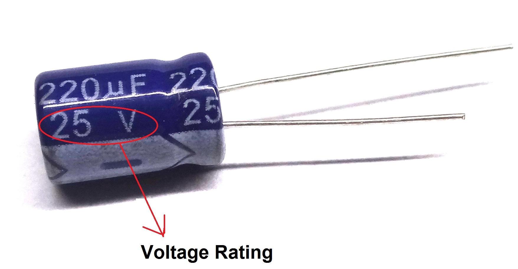
If the capacitor is applied with voltage greater than this voltage, it may be damaged by producing an arc between the plates due to dielectric break down.
While designing the circuits with capacitors, care should be taken such that the voltage rating of the capacitor is greater than the voltage used in the circuit. For example if the circuit operating voltage is 12V then it is necessary to choose a capacitor with voltage rating of 12V or above.
This working voltage of a capacitor depends on the factors like dielectric material used between the capacitor plates, dielectric thickness and also on the type of circuit which is used.

19 Responses
Awesome article… can you please provide download option in pdf format.
@Kavi If you are using Safari, you can easily save the article in PDF. Safari has a feature called “Reader”. You can view the article in Reader mode (SHIFT+CMD+R on Mac or View->Show Reader menu) and save it in PDF. While you are in Reader mode, print the article and you will see “Save as PDF…” option if you are using Mac. I’m not sure if this option exists on Windows.
What a great article.It is very.informative and well written.
Thank you
Ralph
Best article, first I would like to say thanks to you for posting such wonderful article. Can you please explain me how to select value of Capacitance while designing any circuit? As you explain nicely how to select rated voltage capacitor for particular application, just like that can you please tell me how to choose specific value of capacitance value in the circuit.
Awesome article and many many thanks to the uploader , keep it up (y)
realy its evry use full to understanding eveven a poor stdt in a direct to know pareticular pt.
thanks a lot for giving the appartunity.
Thank you so much for this…
i am applying 12V to the capacitor ,which capacitor should i select i mean 1uF/25V or 10uF/25V
how can i calculate the capacitor
thanks for the article
Very interesting to read and will also like to get the ebook of all those electronics components listed.
good enough for beginners in a simplest form.
Really this was awesome…. utilising deep concept in less time.
Thanks for such kind of gainful
article.
Keep it up……
awesome, i got clarity about capacitor.
wonderful explanation loved it. understood about capacitor.
sir/madam, congratulations to such a wonderful information passed out.
how did you identifying the value of capacitor
its really amazing,,but i can’t download it
nice article
very usefull article. Thank you so much for providing this for free.
it’s very easy to understand… good explanation… but I can’t download it..