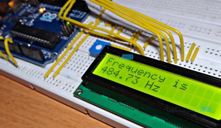
Frequency Counter, as the name indicates, is an electronic device or component, which is used to measure the frequency of a signal. In case of a repetitive electronic signal, a frequency counter measures the number of pulses in that signal.
We generally use an oscilloscope to depict the signal, calculate the time period of the signal and finally convert it to calculate the frequency of the signal. But, oscilloscopes are very expensive and everyone cannot afford it.
Hence, a simple Digital Frequency Counter can be built which might come in handy to measure the frequency of a clock signal, for example.
In this project, an Arduino based Digital Frequency Counter is designed to measure the frequency of an incoming signal.
Frequency Counter Using Arduino Circuit Diagram
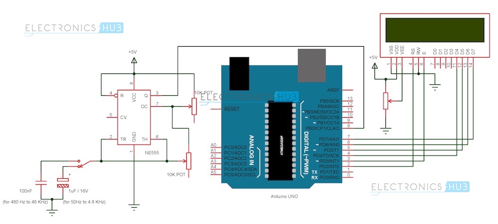
Figure Arduino Frequency Counter Circuit Diagram
Components
Arduino Part
- Arduino UNO [Buy Here]
- 16 X 2 LCD Display [Buy Here]
- Prototyping Board
- Connecting wire
- Power Supply (adapter or battery)
Signal Generator Part
- NE555 Timer IC
- 10 KΩ Potentiometer X 2
- 100 nF Capacitor (Code: 104)
- 1 µF / 16V Electrolytic Capacitor
- 5V Power Supply (12V is not suitable as it might damage Arduino board).
- Connecting wires
- Prototyping Board
Component Description
Arduino UNO: The ATmega 328P microcontroller based Arduino UNO is the main part of the project. It captures the time period of the incoming signal and calculates the frequency of the signal.
555 Timer IC: In this project, the 555 Timer IC is used as a pulse generator i.e. it works in astable mode.
16 X 2 LCD: The 16×2 LCD module is used to display the key information like welcome (or any custom) messages and the calculated frequency of the signal.
Circuit Design
The design of the Frequency Counter using Arduino UNO can be divided in to two parts: The Arduino part, where the processing of the signal’s information takes place and the Signal Generator part, where the signal whose frequency to be measured is generated.
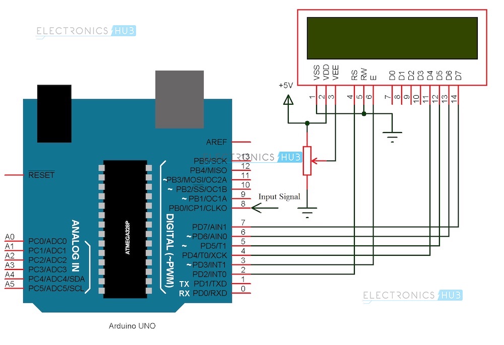
Arduino Circuit
Arduino part of the project consists of Arduino UNO board and a 16 X 2 LCD Display. Pins 1 and 2 of the LCD (Vss and Vdd) are connected to ground and 5V supply respectively. Pin 3 (Vee), which is used to adjust the contrast of the display, is connected a Potentiometer.
Pins 4 and 6 (RS and E) of the LCD are connected to digital I/O Pins 2 and 3 of the Arduino. Pin 5 (RW) of the LCD is connected to ground.
Pins 11 to 14 (D4 to D7) i.e. the data pins of the LCD are connected to the digital I/O pins 4 to 7 of Arduino. Pins 15 and 16 of the LCD are supply pins of the backlight LEDs and are connected to ground and 5V (Pin 16 to 5V through a 1KΩ resistor) respectively.
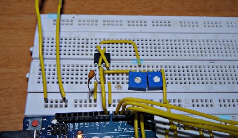
Signal Generator Part
A 555 Timer is used to generate a pulse in this project. Hence, it is operated in Astable mode of operation. The connections for this mode are as follows.
Pins 4 and 8 (Reset and Vcc) are connected to 5V Supply. Pin 1 (GND) is connected to ground. Pins 2 and 6 (Trigger and Threshold) are shorted.
A 10KΩ Potentiometer is connected between the power supply and Pin 7 (Discharge). The wiper terminal of the potentiometer is connected to Pin 7.
Similarly, another 10KΩ Potentiometer is connected between pins 7 and 6. This time, the wiper of the potentiometer is connected to Pin 6.
A 100nF capacitor is connected between pin 6 and ground. By selecting this resistor, the frequency of the output signal, which can be taken from Pin 3 (Output), will be in the range of 480 Hz to 48 KHz.
Optionally, a 1 µF capacitor can be connected, using which the frequency of the generated signal will be in the range of 50 Hz to 4.8 KHz.

Note: The power supply to the signal generator circuit should be only 5V. This is because, the voltage of the generated pulse will be same as that of the input voltage and the Arduino UNO board (or ATmega 328p microcontroller to be precise) can tolerate a maximum of 5.5V at its input pins.
Working Principle of the Project
The aim of the project is to design a simple digital frequency counter circuit using Arduino UNO and 555 Timer IC. The working of the project is very simple and is explained here.
As mentioned earlier, the 555 Timer IC is configured to operate in Astable mode. Hence, the output of the 555 Timer IC (or rather the signal generator circuit) is a pulse with variable frequency (varied using potentiometer). This pulse is given as input signal to the Arduino UNO at one of its digital I/O pins.
In the Arduino, we make use of a function called “pulseIn ();” The function pulseIn can be used to read either LOW or HIGH pulse on a digital I/O pin and returns the length of the pulse in microseconds.
For example, if the pulseIn function is used to read a HIGH pulse on a pin, it waits for the pin to go HIGH. Once the pin goes HIGH, it starts the timer and runs until the pin goes LOW. The duration (in microseconds) of this HIGH pulse is then returned.
In our project, we are calculating the duration of the HIGH pulse and LOW pulse and by adding them together, we get the period of the input signal. Inverse of this value gives the frequency of the signal which is displayed on the LCD.
Note:
- As mentioned earlier, the range of frequency of the signal generated by the 555 Tier can be changed by changing the value of the capacitor.
- Arduino can only detect incoming pulses i.e. the incoming signal can be either square or rectangular. Not all test signals can be in the form of pulses. Hence, we can use a Schmitt Trigger to convert the any incoming to a pulse.
- Also note that the output of the Schmitt Trigger IC (74LS14) is an inverted signal of the input signal.
Applications
- A simple frequency counter, using simple components is designed that can be used to measure the frequency of a pulse without the need of an oscilloscope.
- Multiple ranges of frequencies can be measured by selecting suitable components.
- Frequencies of all types of test signals can be calculated by adding a Schmitt Trigger between the generated signal and Arduino.

13 Responses
I executed the circuit but I am getting areading of “inf Hz”… what might be the problem???? Thanks:)
Hi, If you are getting inf Hz, it means the duration of the pulse (HIGH Pulse + LOW Pulse) is very close to 0. Try to check the pulse generator circuit once.
hello sir/madam
i am working on this project all connections made as per above circuit diagram.But it has some error some time it shows frequancy and after sometime it just shows inf Hz i am trying to check all the possibilty of error but it seems good. Plz help me to sort it out
with regards
hope u will reply soon
Hi, If you are getting inf Hz, it means the duration of the pulse (HIGH pulse + LOW Pulse) is very close to 0. Try to check the pulse generator circuit once.
which timer is used here? I mean as per above discription, when pulseIn() function is used timer gets on…..here which timer gets on?
Hi,
I went ahead and created the LCD screen hardware output then the signal generating hardware and it worked like a charm, except the sign on frequency is negative. Would that be a hardware issue or software issue? Any tips on figuring that out would be helpful.
I have thesame problem.
how can we say that 555 ic timer is generating a signal
Best way to check is using an Oscilloscope.
const int pulsePin = 8; // Input signal connected to Pin 8 of Arduino
int pulseHigh; // Integer variable to capture High time of the incoming pulse
int pulseLow; // Integer variable to capture Low time of the incoming pulse
float pulseTotal; // Float variable to capture Total time of the incoming pulse
float frequency; // Calculated Frequency
void setup()
{
// put your setup code here, to run once:
Serial.begin(9600);
}
void loop()
{
pulseHigh = pulseIn(pulsePin, HIGH);
pulseLow = pulseIn(pulsePin, LOW);
pulseTotal = pulseHigh + pulseLow; // Time period of the pulse in microseconds
frequency = 1000000 / pulseTotal; // Frequency in Hertz (Hz)
Serial.print(frequency);
Serial.println(" Hz");
delay(500);
}
Good Morning,
How can I use an antenna to receive the signal.
I want to check a signal from a 433 MHz remote.
Thank you.
i am using an external device to feed the arduino circuit. the read out stops at 200kHz – it would occasionally flicker to 250kHz but then back to 200kHz. . any way to fix that part? Trying to adjust something to 262kHz using this readout. The lower frequencies seem to work ok on input.
What are the potentiometers connected to pins 6 and 7 used for in the signal gen portion of the circuit?