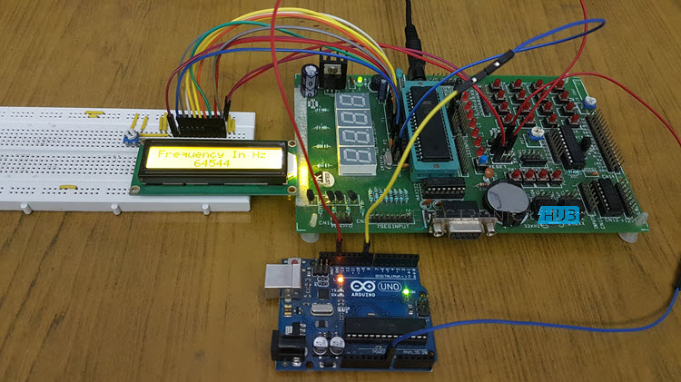
In this project, I will design and demonstrate a simple Frequency Counter Circuit, which can be used to measure the frequency of a signal. This project is based on 8051 Microcontroller, although you can design a non-microcontroller version.
Introduction
A frequency counter is an instrument that is used to measure the frequency of a signal. In scientific terms, frequency is the number of cycles per second of a signal. In layman terms, frequency of a signal denotes the rate of occurrence of the signal in certain time. Frequency Counters are basically simple counter systems with a limited time period for counting.
Here we design a simple frequency counter system using two timers and two counters. While one of the Timer IC is used to produce clock signals, the other is used to produce the time limited signal of one second.
Also Read the Post – Two Digit Up-Down Counter Circuit
Frequency Counter Circuit Operating Principle
This circuit is based on the simple definition of frequency, which is the number of cycles per second. Basically, a Square Wave Generator circuit is used to produce a simple pulse wave. These pulses are given as input to the Timer / Counter of the 8051 Microcontroller and count the number of pulses.
After performing some simple calculations, the resulting frequency is displayed on a 16X2 LCD Display in Hertz.
An important point to note is that I have used Arduino UNO as the source for Square Wave. You can use either Arduino or a completely build your own Square Wave Generator using 555 Timer IC by configuring it as an Astable Multivibrator.
Frequency Counter Circuit Diagram
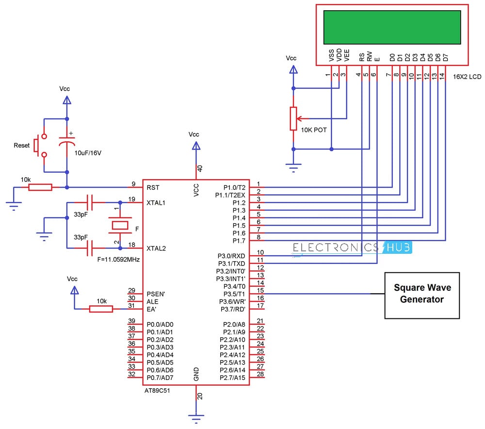
Frequency Counter Circuit Design
As I have used Arduino to generate the Square Wave, all I need is a few lines of code and access to a single Digital I/O Pin. But if you are planning to build a Square Wave Generator circuit using 555 Timer IC, the understand the following explanation.
The primary requirement in the 555 Timer circuit is to generate an oscillating signal with a duty cycle of about 99% such that the time low value is less than the time high value of the output signal. Since duty cycle depends only on the value of the threshold and discharge resistors, it can be adjusted by selecting the proper values of resistors.
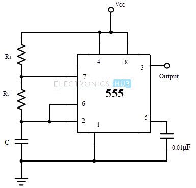
The duty cycle is given by D = (R1+R2)/(R1+2R2)
Substituting the value of D to be 0.99, we get the value of R1 to be 98 times the value of R2. Thus, selecting a value of 100Ω for R2 and 9.8KΩ for R1. Practically the value of 10KΩ is chosen for R1.
Next step in the designing of the circuit is the design of the counter circuit. Here our requirement is the measurement of frequency of the order of few Kilo Hertz. As mentioned in the circuit principle, I will be using the Timer / Counter of 8051. In fact, I will be using both Timer 0 and Timer 1 of the 8051 Microcontroller.
I will be using Timer 0 to generate Time Delay and Timer 1 to count the Pulses coming from the pulse generator. Timer 0 is configured as Timer in Mode 1 while Timer 1 is configured as Counter in Mode 1.
Do you about the concept – Bi Directional Visitor Counter using 8051 Microcontroller
Code
Following is the code for Frequency Counter Circuit using 8051 Microcontroller.
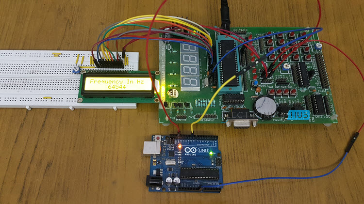
Frequency Counter Circuit Operation
Make the connections as per the circuit diagram and apply the Pulse generated by Arduino at Port 3 Pin P3.5, which is the Timer 1 Pin. As I have configured the Timer 1 as counter, using the TCON Bit TR1, I will be counting the pulses for a duration of approximately 100 milliseconds by making TR1 HIGH and LOW. The count of the pulses is stored in Timer 1 i.e. in TH1 and TL1 Registers.
To get the value of the frequency, you have to use the following formula.
frequency=(TH1*256)+TL1;
In order to convert the Frequency Value to Hertz i.e. Cycles per Second, you need to multiply the resultant value by 10. After this, the resultant value is formatted by performing some simple mathematics so that it will be easy to display the result on the 16X2 LCD Display.
Applications of this Circuit
- The Frequency Counter Circuit using 8051 Microcontroller can be used to accurately measure the frequency of a signal.
- Since we are counting pulses, we can measure the frequency of only square waves and its derivatives (with different duty cycles.)

3 Responses
how to work in electonice component
I need all the requirements for the frequency counter circuit of this diagram which is given above .
can you email me the apparatus required for this project . It will be helpful for me if you do this please send me on rs.nobody104@gmail.com
Regards
.
Hey! you had design frequency counter?
I need some help.