Generally, you can see the digital displays which display the score when buttons are pressed on score boards. The main heart of this score board is 2 digits up down counter circuit. The 2 digits are displayed on two 7 segment displays.
In this project, I will show you how to build a 2 digit up down counter circuit using both 8051 Microcontroller and ATmega8 Microcontroller.
2 Digit Up Down Counter Circuit Principle
Main principle of the 2 Digit Up Down Counter circuit is to increment the values on seven segment displays by pressing the button. When button 1 is pressed, the value on the display is incremented by one and when the other button is pressed, the value on the display is decremented by one.
The value on the display can be incremented and decremented from 0-99 as it uses only 2 displays. If you want to display 3 digits, three displays should be used i.e. three 7-Segment Displays. There are many circuits available for 2 digit up/down counter but using a microcontroller reduces components and space on the board but simple programming is required.
Also Read the Related Post – Frequency Counter Circuit
Two Digit Up Down Counter Circuit Diagram
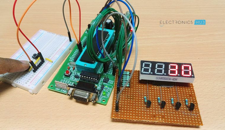
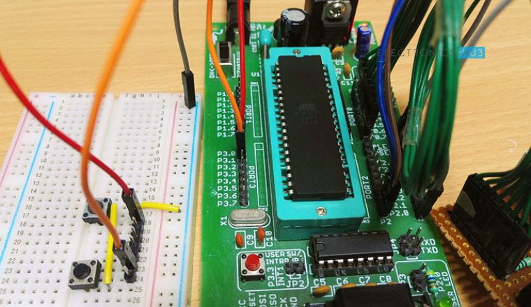
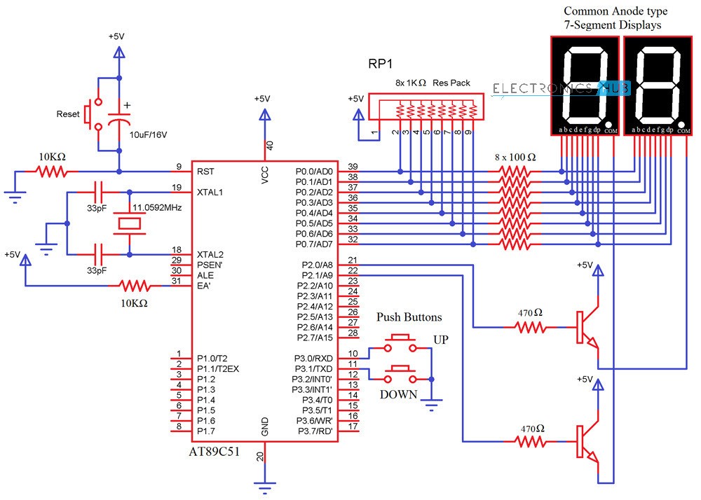
Circuit 1: Using 8051 Microcontroller
Components Required
- AT89C51 (8051 Microcontroller)
- 2 X 7-Segment Displays (Common Anode)
- 2 X 2N2222 NPN Transistors
- 3 X Push Buttons
- 2 X 10KΩ Resistors
- 2 X 470Ω Resistors
- 8 X 100Ω Resistors
- 11.0592 MHz Crystal
- 2 X 33pF Capacitor
- 10μF/16V Capacitor
- 1KΩ X 8 Resistor Pack
- Mini Breadboard
- 5V Power Supply
- 8051 Programmer
Circuit 2: Using ATmega8 Microcontroller
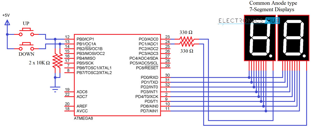
Components Required
- ATmega8 Microcontroller
- 2 X 7-Segment Displays (Common Anode)
- 2 X 10KΩ Resistors
- 2 X 330Ω Resistors
- 2 X Push Buttons
Circuit Design of 2 Digit 7-Segment Up Down Counter
The 2digit Up/Down counter consists of two seven segment displays connected to ATMEGA8 microcontroller. The seven segment display consists of 8 pins and one common pin.
There are mainly two types of seven segment displays 1) common cathode 2) common anode. The display here used is common cathode display. Generally for common cathode displays, common pin should be grounded and for common anode, it should be connected to VCC.
In Seven segment display, there are seven segments and they are similar to seven LEDs. Seven pins belong to these seven segments where as the last pin is dot at the coner of the display. For common cathode, display assigning logic1 to the segment pin glows particular segment. In case of common anode, the segment pin should be assigned logic0 in order to glow the segment. Each segment is given one name starting from ‘a ‘and last segment dot is ‘h’.
In our circuit, seven segment display is connected to micro controller through a current limiting resistor of 330 ohms. Two buttons in pull- down mode are also connected.
The necessity of connecting the buttons in pull down mode is to avoid floating state of the button i.e. unknown state. If the button is connected in pull down mode, this ensures that button is initially in logic0 state.
Do you know How a Bidirectional Visitor Counter Circuit Works using 8051 Microcontroller?
Two Digit Up Down Counter – Circuit Simulation Video
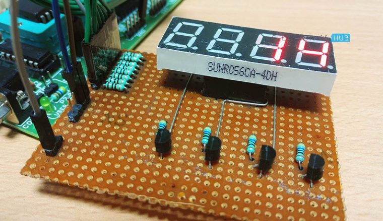
How to Operate 2 Digit Up Down Counter Circuit?
- Initially, power the circuit.
- The values displaying on seven segments is ‘00’.
- Press the button 1 in the circuit. The value on the seven segments is incremented to ‘01’.
- Again press button 1. Value on the displays is ’02’.
- Now, press the second button. You can see the value decrementing to 01.
- The value on the displays can be incremented up to 99, after 99 if button 1 is pressed it starts incrementing from ‘01’. If the second button is pressed after decrementing to ‘00’, it displays ‘00’. This value can be changed only after incrementing the value atleast to ‘01’.
Algorithm for Programming
- Declare the corresponding PORTS of the microcontrollers as input or output.
- Declare an array with the seven segment codes i.e, if number one is to be displayed, then the binary value that should be passed is as follows:
dp g f e d c b a
1 1 1 1 1 0 0 1
This is because b and c segments should be assigned with logic 0 to display ‘1’, I am using a Common Anode 7-Segment Display . So, the binary value 0b11111001 or the hexadecimal value 0xf9 is assigned to the particular port on which ‘1’ is to be displayed. The array should consist of 0-9 binary or hexa values.
- Check the status of the buttons using if else loop.
- If the button 1 is pressed for first time, first seven segment (on the left) should display 0 and the other should display 1. So the output is ‘01’.
- If the button 1 is pressed for second time, value on second button should be incremented by one.
- If the second button is pressed, value on the first segment should be decremented by one value.
CODE
Code for 8051 Microcontroller
Code for ATmega8 Microcontroller
2 Digit Up Down Counter Circuit using ATmega8 Output
2 Digit Up Down Counter Circuit Applications
- This circuit can be used in scoreboards.
- Up/down counter is used for counting number of objects passed through a point.
- It is used to count number of persons entering a room.
Limitations of this Circuit
This particular Up/Down Counter circuit is limited to 2 digits i.e. 0-99. If more than 3 digits are required, one should use another display which requires more pins from the controller.

48 Responses
good day, i am making projects which is same feature in this article but i am only using the 74ls192 and 7447. I want to change it using arduino. But i’m just a beginner. Is it possible to have your code..
Thank you very much
Best regards
i have to submit the same project in my college.So,please provide me the code.
NOT ABLE TO FIND THE CODE ,…PLEASE MAKE LEARNERS VISIBLE
THANK U
i need this project for my college exhibition.So,please provide me the code. Thank you.
I want this code please, I want used it for practice I am just a beginner…. Thank you so much
hi and thank’s
the project title is one of my project i need it to modify mine
by the way i’m doing this by using VHDL(Hardware deschription language)
have a nice job
I want this code, i just want to know the idea of up and down counter.. because i need to apply it to my homework.. i hope u can help me.. thanks..
Code is uploaded in the article .Please go through it..
give us the code please, we want to use it for project for our assignment by next wek
can i have this coding?
Hi, I need to do project for my Microcontroller class. its a bit different from this one because we’re trying to use 3 seven segments. but your code could really help me and my teammates. thanks.
– to do my Microcontroller project.
– a bit different.
– 3 seven segments.
could really use your help. thank you. best regards
i need this for my Microcontroller mini-project. it is same project s this one. we could really use your help. thanks. best regards.
Hi,
I’m making a spaceship for my little boy who’s nearly two. It’s going to be a tent-type arrangement with a console and a joystick that he will sit behind where he will be the captain and control the ship through our bedtime stories/adventures. We’re integrating Skype and Facetime in there so we can talk to whoever, who’ll be pretending to be ground control or the like. We’ll have headphones and mics that’ll be driving various LM3914’s acting as spectrum analysers with an array of flashing LEDs on the console. Your counter circuit will be for the weapons systems where the up button will be on my side to ‘load’ ammo and rockets, and the down button will be routed from the joystick. A Raspberry Pi will be triggering all the sound effects. I think with a bit of modification to your code another counter circuit can also represent a fuel gauge which will decrement on a timer loop. All of this stuff will be a brilliant way of teaching him basic numeracy. I’m also hoping that he might just get interested enough to learn this stuff for himself as he grows.
I’d very much appreciate it if you would be kind enough to supply me with your code. I’ve never written any C before, but I’m ok-ish with Perl and understand code structuring, so I’ll be able to follow it and make my necessary changes.
HAI CAN YOU DESPLAY THE COMPONENTS OF LOGIC COUNTER AND CAN I ASK FOR 1 LOGIC DRIVER WITH PUSH BUTTON I NEED IT IN OUR PROJECT
I AM INDUSTRIAL ELECTRICIANS NEED OF YOUR HELP
Hello I need the programing codes really quick , I have a exam tomorrow at microcontrollers , I need to present the codes that I “wrote” for this circuit . I only use in this purpose
kindly send me code ….
-I need the code to make a mini project
-Since this is the first Time i am going to make a mini project i’m going to make the same project as given in your website.
Thank you
Want it for my class project.
It is a bit different . I have to show up and down counting and then stop it at a specific value i.e. my class
hello, i really need the code for our school project. We were tasked to make a counter teller. I don’t know a lot about circuits. Your code would really be a big help in making our project…
-Thanks
We have already uploaded the code in the article Please check it once..
Um, I can’t see the code on this article. .
Below the simulation video a link is given to download the code….If you cannot find it there also go to the top of article..there ,please check in the contents…
Please send me the code. I wanna make score board using arduino. Is there any different?
Code is uploaded in the article.Download code from there..
I am doing sum odr microcontroller projct…but just to get sum idea on coding…i needed the coding part of dis projct
Downlaod code from the post itself
What happens when both buttons are pressed simultaneously?
Hello, I’d like to have a look at your MC code. I’m a total software noob, hardware i can take care of. I’d like to make the project as part of my final year(developing several energy saving compact devices), but with a little tweak to your counter; i”ll be using two PIR sensor as the input… I’d like this project done and out of the way this week if you’ll be so kind.
i have to submit a project which is a little similar to this one. can you please provide the code
for learning process pls provide me the code
Hi,
Would the code work if I use an Atmega16-8ML.
Also, how would I go about if I use 4 displays?
Would anyone be interested in halping me design a PCB for this?
I want to do project for project based learning in my college and I want to submit it .So please provide me code
I found this project interesting and having ideas to use this concept and improvise to develope my own project and please provide the code.
hello all.i am doing object counter using 88s52uC as my final year project but i can’t help it as i have tried all my best.please it would be a great pleasure if your assistance is given.note,i am using keil ide.regards.looking forward to your responses asap
Hello sir/ma’am,
I’m Kishan & now i’m looking for minor project. I’m making motor winding machine which is different from market machine. Because market machine take time upto 16-17minute {ideally} but my machine take the time upto 3-4 minute {ideally} for winding a wire on primary & secondary. Sometimes ago i was made only with 7410 & 7411 but there were some faults occurred. So i need this type of counter circuit which include an option for #preset the value of counting turns.
Hope you may help me to making this machine. Because in really it’s not any type of project but Hobby.
I start working on ESP8266 wi-fi module to make a counter, therefore i need code.
hi..
can i have your coding please…
i want to use as a reference for my mini project..
i use ir sensor as a input..
one for counting up and another for counting down..
I am working on a project that only needs a two digit LED display to indicate the number status of an audio mixer sound effects module. This would work nicely and save me time in it’s simplicity. It would be greatly appreciated if you would send me the code needed for this device. Thank you.
i m a beginner… i need it for learning….
Nice
i have a programming code in my college mini project . so send in programming code . otherwise very nice . i like this mini project
I have a code atmega8 .two digit ssd when i pressed up button maximum value giving the garbage value.plz can you help me
Can the ATmega8 code work with with pic16f877
No.
Will the code work on Atmega328 microcontroller?
i have to sub,it the same project but i am using the PIC18f4580 ,So i need the need the code according to that