We will learn about Ex OR Gate in this tutorial. Ex OR gate is the Exclusive OR gate. This is not frequently used as inclusive OR gate, which is nothing but the regular OR gate. XOR gate has its own significance. We will learn the symbol, truth table of XOR Gate, implementation using other gates (AND, OR, NAND, NOR), popular XOR ICs and some important applications of Exclusive OR Gate (XOR Gate).
XOR Gate
Exclusive OR Gate, also known as EX OR Gate or XOR Gate, is an important digital logic gate, which implements an exclusive or logic i.e., the output is HIGH if and only if one of the inputs is HIGH. If both the inputs are LOW or HIGH, then the output is LOW.
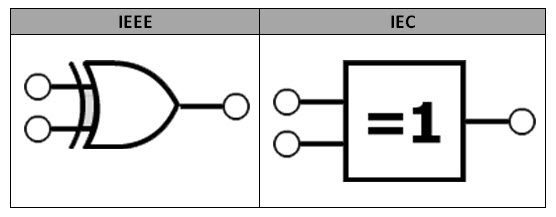
XOR Symbol
There are multiple standards for defining an electronic component. Generally, we follow the IEEE (Institute of Electrical and Electronics Engineers) and IEC (International Electrotechnical Commission) standards. The XOR logic symbol in IEEE and IEC standards is shown below.
The Boolean expression for XOR gate cannot determined directly like AND, OR gates. As it is a Hybrid gate, the Boolean expression of output of XOR gate is given by a combining of Multiplication, Addition and inverting of inputs. We have to use the Karnaugh Maps or K – Maps along with the truth table to derive the Boolean Expression of XOR gate.
XOR Truth Table
The truth table of XOR gate is shown in the below table. From this, it is clear that XOR gate produces a logic LOW i.e., Logic ‘0’ at its output, when both the inputs are same (both may be LOW or both may be HIGH).
low logic that is logic ‘0’ , at its output , when When the two inputs are different it produces a logic high value i.e., logic ‘1’ at its output.
| Inputs | Output | |
| A | B | Q |
| 0 | 0 | 0 |
| 0 | 1 | 1 |
| 1 | 0 | 1 |
| 1 | 1 | 0 |
The K-map representation of the above truth table of the XOR Gate is shown below.
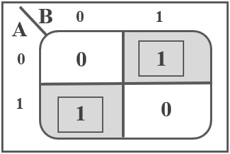
XOR Boolean Expression
Using the above truth table and corresponding K-Map, we can now derive the Boolean Expression for XOR Gate. If A and B are the inputs of the XOR gate, its output is given as:
A B + A B
The XOR output is represented as:
A ⊕ B
It can also be written as:
(A + B) (A + B)
By applying De Morgan’s law, the above Boolean expression can also be written as:
(A + B) (A B)
XOR Gate Equivalent Circuit
The EX-OR gate is defined as a hybrid logic gate with 2 inputs to perform the Exclusive Disjunction operation. From the above calculations, the main Boolean Expression of XOR gate is:
A B + A B
So, the XOR circuit with 2 inputs is designed using AND, OR and NOT gates as shown below.
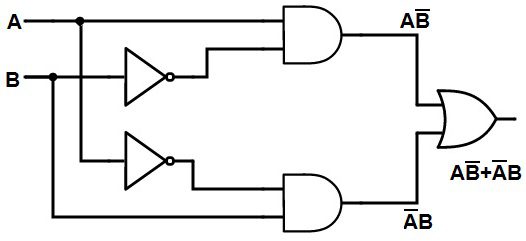
The output of 2 input XOR gate is HIGH only when one of its inputs are HIGH. If both the inputs are same, then the output is LOW.
XOR Gate using Basic Logic Gates
If a specific gate is not available directly, we can design the XOR Gate by using multiple gates. An EX-OR gate can be designed by using basic logic gates like NAND gate and NOR gate as they are universal gates.
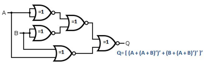
With NOR Gates
Let us now see how we can implement the XOR Gate using NOR Gates. For this, we have to re-write the above XOR Boolean Equation.
Q = A B + A B
Q = A B + A B + A A + B B
Q = ( A + B ) (A + B)
Q = ( A + B ) (A + B) = (A’ + B’) (A + B)
Taking complement on both sides, we get:
Q = ((A’ + B’) (A + B))
Using de Morgan’s Law, we get:
Q = (A’ + B’) + (A + B) = (A’ + B’)’ + (A + B)’
Once again taking complement on both sides, we get:
Q = ((A’ + B’)’ + (A + B)’) = ((A’ + B’)’ + (A + B)’)’
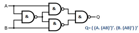
This equation looks like it can be implemented using NOR Gates. We need totally five NOR gates (two for inverting A and B, one for NOR of A and B, one for NOR of A’ and B’ and the final one to obtain the above equation). The following image shows the XOR Gate implemented using NOR Gates.
With NAND Gates
Let us now see how we can implement the XOR Gate using NAND Gates. For this, we have to re-write the above XOR Boolean Equation.
Q = A B + A B
Q = A B + A B + A A + B B
Q = (A + B) ( A + B )
Q = (A + B) ( A + B ) = (A + B) (A’ + B’)
Applying de Morgan’s Law on the second term in the above equation, we get:
Q = (A + B) ( A B )
Now we need to implement this circuit using NAND gates.
Q = A ( A B ) + B ( A B ) = A (AB)’ + B (AB)’
Taking complement on both sides, we get:
Q = (A ( A B ) + B ( A B ))’ = (A (AB)’ + B (AB)’)
Q = (A ( A B ))’ (B ( A B ))’ = (A (AB)’) (B (AB)’)
Finally, once again, apply complement on both sides.
Q = (A ( A B )’)’ (B (A B)’)’ = ((A (AB)’)’ (B (AB)’)’)’
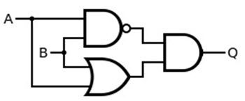
This equation looks like it can be implemented using NAND Gates. We need totally our NAND gates. The following image shows the XOR Gate implemented using NAND Gates.
Using AND, OR and NAND Gates
Let us now see how we can implement the XOR Gate using NAND, AND and OR Gates. For this, we have to re-write the above XOR Boolean Equation.
Q = A B + A B
Q = A B + A B + A A + B B
Q = (A + B) ( A + B )
Q = (A + B) ( A + B ) = (A + B) (A’ + B’)
Applying de Morgan’s Law on the second term in the above equation, we get:
Q = (A + B) ( A B )
The first term in the above equation requires an OR Gate, the second term needs a NAND gate and the final equation can be obtained using an AND gate.
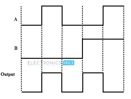
Pulsed Operation of XOR Gate
The pulsed operation of 2 input XOR gate is shown below.
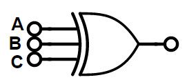
3-Input Ex-OR Gate
In some cases, we need to have XOR Gates with more than 2 inputs. More than 2 input XOR function is called as “Odd function” or “Modulo-2 sum”. The Boolean function for the 3- input XOR gate is:
Q = A ⊕ B ⊕ C = A B C + A B C + A B C + A B C
The truth table and logic symbol for 3-input XOR gate is given below.
3-Input Ex-OR Gate Logic Symbol
Truth Table of 3 Input XOR Gate
For 3-input XOR gates, we can have the HIGH input when odd numbers of inputs are at HIGH level. So the 3-input OR gate is called as “Odd functioned OR gate”.
| Inputs | Output | ||
| A | B | C | Q |
| 0 | 0 | 0 | 0 |
| 0 | 0 | 1 | 1 |
| 0 | 1 | 0 | 1 |
| 0 | 1 | 1 | 0 |
| 1 | 0 | 0 | 1 |
| 1 | 0 | 1 | 0 |
| 1 | 1 | 0 | 0 |
| 1 | 1 | 1 | 1 |
Commonly Available TTL and CMOS Logic Ex-OR gate IC’s
Following is a list of some of the commonly available XOR ICs.
| IC Number | Description |
| 4030 | Quad 2-Input XOR Gates |
| 4070 | Quad 2-Input XOR Gates |
| 7486 | Quad 2-Input XOR Gates |
| 74LS86 | Quad 2-Input XOR Gates |
| 741G86 | Single 2-input Ex-OR Gate |
| 74136 | Quad 2-Input XOR Gates with Open Collector Outputs |
| 74386 | Quad 2-Input XOR Gates |
Of these, the most popular TTL Logic based EX-OR Gate IC is the 74LS86, which is a Quad 2-input XOR IC. Coming to the CMOS Logic based XOR Gate IC, the CD4030 Quad 2-input XOR IC is a popular choice.
7486 Quad 2-Input Exclusive-OR Gate IC
IC 7486 is a quad 2-input XOR gate i.e., it contains four 2-input XOR Gates in a single package. The pin diagram and pin description of the IC is shown below.
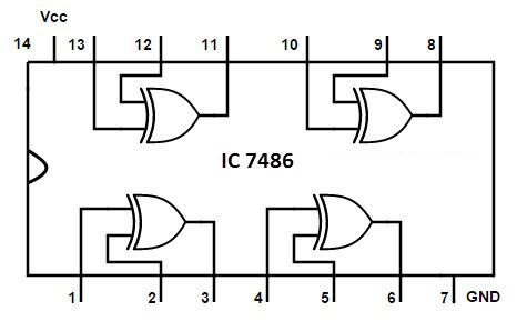
| Pin Number | Description |
| 1 | Gate 1 Input A |
| 2 | Gate 1 Input B |
| 3 | Gate 1 Output Y |
| 4 | Gate 2 Input A |
| 5 | Gate 2 Input B |
| 6 | Gate 2 Output Y |
| 7 | Ground |
| 8 | Gate 3 Output Y |
| 9 | Gate 3 Input A |
| 10 | Gate 3 Input B |
| 11 | Gate 4 Output Y |
| 12 | Gate 4 Input A |
| 13 | Gate 4 Input B |
| 14 | Positive Supply |
Applications of Ex-OR Gate
XOR Logic Gate is used in many applications. Some of them are explained below.
Used in Adder (Addition)
We can design single bit adder (also known as Half Adders), which will add two bits and produce a single bit output. The single bit Adder designed by using XOR gate is shown below.
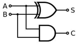
For example, if we add two bits ‘1’ and ‘1’ in binary addition, we get the answer ’10’ and in decimal addition method we get 2. The main principle of half adders is that the trailing sum is achieved by the output of XOR gate and the carry bit is calculated by AND gate.
We can cascade many single bit adder circuits to form n-bit adder circuit, to calculate the sum of longer binary numbers.
Pseudo-Random Number Generation
Linear shift registers are also called as Pseudo Random Number Generators (PNRs). In order to generate the random numbers, we arrange the XOR logic gate in a specific order by forming a linear feedback shift register.
Correlation and Sequence Detection
XOR gate is capable of producing a low level input i.e., 0, when all of its inputs are HIGH or LOW. When we are searching for a particular bit sequence in a long data sequence, we use XOR gates to find the required data bit sequence.
The accuracy of finding the required string of data bits in the target sequence is determined by calculating the number of 0’s obtained. In many communication devices such as decoders and CDMA receivers, we use co-relaters, which are used to extract the parity of a specific Pseudo Random Number sequence in a group of PRN sequence.
Conclusion
A complete tutorial on Exclusive OR Gate (XOR Gate). You learned the symbol, truth table and Boolean Expression of an XOR Gate, implementation of XOR Gate using NOR and NAND gates, a 3-input XOR Gate, its symbol, truth table and Boolean Expression, some common and popular XOR ICs and also some important applications of XOR Gate.
