In this tutorial, we will learn about Diode Clippers and Clampers. Even though rectification is the basic application of diodes, Clippers and Clamper circuits are equally important. Clippers are known as Limiters and Clampers are known as DC Restorers. This tutorial gives an in-depth information about Diode Clippers and Clampers.
Diode Clippers
Most of the electronic circuits like amplifiers, modulators and many others have a particular range of voltages at which they have to accept the input signals. Any of the signals that have an amplitude greater than this particular range may cause distortions in the output of the electronic circuits and may even lead to damage of the circuit components.
As most of the electronic devices work on a single positive supply, the input voltage range would also be on the positive side. Since the natural signals like audio signals, sinusoidal waveforms and many others contain both positive and negative cycles with varying amplitude in their duration.
These waveforms and other signals have to be modified in such a way that the single supply electronic circuits can be able to operate on them.
The clipping of a waveform is the most common technique that applies to the input signals to adapt them so that they may lie within the operating range of the electronic circuits. The clipping of waveforms can be done by eliminating the portions of the waveform which crosses the input range of the circuit.
Clippers can be broadly classified into two basic types of circuits. They are:
- Series Clippers
- Shunt or Parallel Clippers
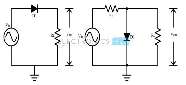
Series clipper circuit contains a power diode in series with the load connected at the end of the circuit. The shunt clipper contains a diode in parallel with the resistive load.
The half – wave rectifier circuit is similar to a series clipper circuit. If the diode in a series clipper circuit is in forward bias condition, then the output waveform at the load follows the input waveform. When the diode is in reverse bias and it is unable to conduct current, the output of the circuit is nearly zero volts.
The direction in which the diode is connected determines the polarity of the clipped output waveform. In case of Series Clipper Circuits, if the diode is reverse biased i.e., Cathode is connected to the positive terminal of the supply and Anode to the load, the circuit will be a Positive Series Clipper, as it clips off the positive half cycle of the input sinusoidal waveform.
If the diode is forward biased i.e., Anode is connected to positive of power supply and Cathode to load, then the circuit will be a Negative Series Clipper, as it clips off the negative half cycle of the input sinusoidal waveform.
The series clipper diode has an output voltage of VOUT = VIN, when the diode is conducting and when it is not conducting, the input voltage applied by the supply will be dropped and has an output voltage of VOUT = 0 V.
In contrast to the Series Clipper Circuit, a Parallel Clipper circuit provides the output when the diode is connected in reverse bias and when it is not conducting. When the diode is non–conducting, the shunt combination diode acts as an open circuit and both the series resistor and load resistor acts as a voltage divider. The output voltage will be calculated as:
VOUT = VIN [RLOAD / (RLOAD + RSERIES)]
When the diode is conducting, it acts as a short circuit and the output voltage across the load will be VOUT = 0 V. The series limiting resistor is connected in series with the supply to prevent the diode from short circuits.
In this case, the output voltage of the circuit should be ±0.7 volts. It depends on the polarity of the shunt clipper which is determined by the direction of diode connection.
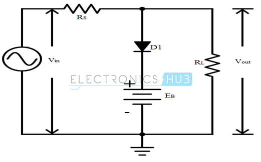
Above circuit is a shunt clipper circuit which uses the DC supply voltage to bias the diode. It is the biasing voltage at which the diode starts conducting. The diode in the shunt clipper circuit starts to conduct when it reaches the biasing voltage.
Clipper circuits are used in a variety of systems to perform one of the two functions:
- Altering the waveform shapes
- Protecting the circuits from transients
The first application is commonly noticed in the operation of half-wave rectifiers that changes an alternating voltage into an output pulsating DC waveform. A transient is defined as an abrupt change in current or voltage with extremely short duration. Clipper circuits can be used to protect the sensitive circuits from transient effects.
Types of Clipper Circuits
Series Negative Clipper
This is the basic clipper circuit using a diode and it nothing but a Half Wave Rectifier. From the following circuit, it is clear that the diode is forward biased during the positive cycle and it acts as a closed switch. Hence, the output voltage is equal to the positive half of the input voltage.
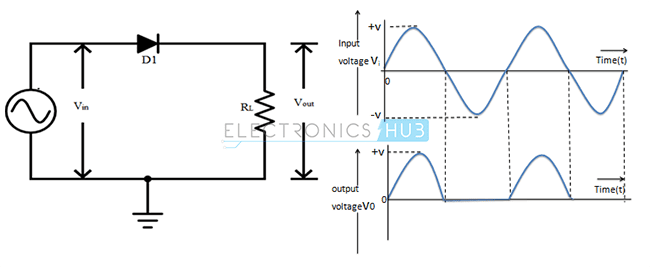
During the negative cycle, the diode is reverse biased and acts as an open switch. As a result, the output voltage is zero.
- Output voltage (VOUT) during Positive Half Cycle = (VIN – VD) Volts
- Output voltage (VOUT) during Negative Half Cycle = 0 Volts
where, VD is the Threshold Voltage of the Diode. If the diode is ideal, then VD = 0 V.
Series Positive Clipper
Simply by reversing the diode, we can obtain a positive clipper configuration as show in the following circuit.
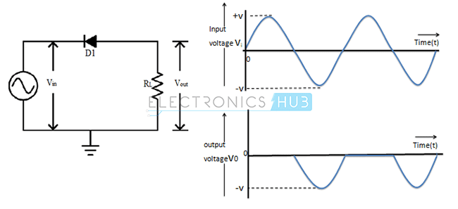
Cathode is connected to the positive of the power supply and anode is connected to the load, which makes diode reverse biased for positive cycle and forward biased for negative cycle.
- During Positive Half Cycle: Output voltage (VOUT) = 0 V
- During Negative Half Cycle: Output voltage (VOUT) = (VIN + VD) Volts
Where, VD is the Diode Threshold Voltage.
Shunt Positive Clipper
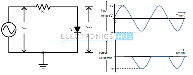
Anode is connected to the the power supply through a resistor R and the cathode is at ground potential.
- During Positive Half Cycle: Output voltage (VO) = Vd Volts
- During Negative Half Cycle: Output voltage (VO) = Vin Volts
Shunt Negative Clipper
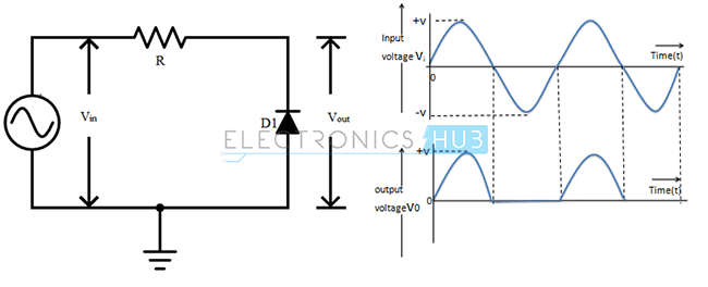
Cathode is connected to the power supply through a resistor R and anode is maintained at ground potential.
- During Positive Half Cycle: Output voltage (VO) = Vin Volts
- During Negative Half Cycle: Output voltage (VO) = – Vd Volts
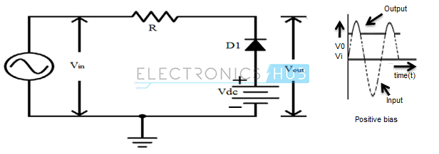
Series Positive Clipper with Positive Bias Voltage
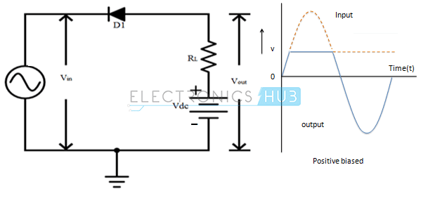
Positive Half Cycle: Cathode is connected to the positive supply and the anode is maintained at positive bias potential.
- When Vin < Vd + Vdc, Output Voltage (VO) = (Vin + Vd) Volts
- When Vin > Vd + Vdc, Output Voltage (VO) = + Vdc Volts
Negative Half Cycle: Cathode is connected to the negative supply and anode is maintained at positive bias potential.
- Output voltage (VO) = (Vin + Vd)
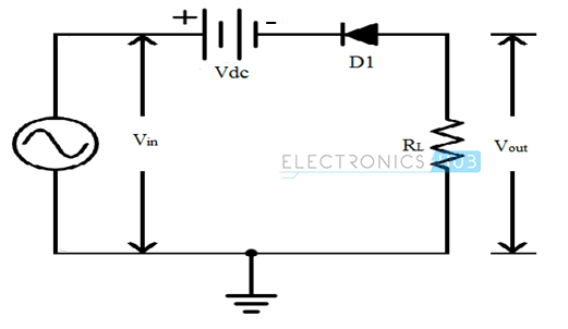
Series Positive Clipper with Positive Bias Voltage Connected in Series
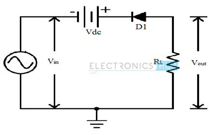
Positive Half Cycle: Anode is maintained at ground potential and cathode is connected to a positive voltage. The diode is reverse biased during the whole positive half cycle.
- Output Voltage (VO) = 0 Volts
Negative Half Cycle: Anode is maintained at ground potential and cathode is connected to a negative supply.
- When Vin < Vd + Vdc, Output voltage (VO) = 0 Volts
- When Vin > Vd + Vdc, Output voltage (VO) = (Vin +Vdc +Vd) Volts
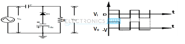
Series Positive Clipper with Negative Bias Voltage
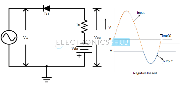
Positive Half Cycle: Cathode is connected to the positive supply and the anode is maintained at negative bias potential.
- Output Voltage (VO) = -Vdc Volts
Negative Half Cycle: Cathode is connected to the negative supply and anode is maintained at negative bias potential.
- When Vin < Vd + Vdc, Output Voltage (VO) = – Vdc Volts.
- When Vin > Vd + Vdc, Output Voltage (VO) = (Vin + Vd) Volts.
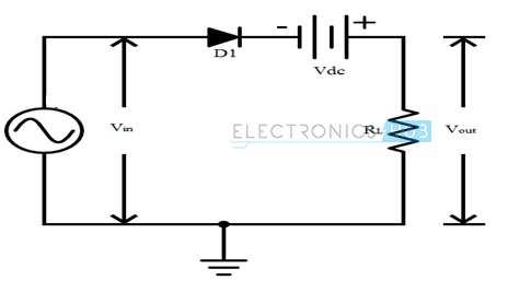
Series Positive Clipper with Negative Bias Voltage Connected in Series
Positive Half Cycle: Anode is maintained at ground potential and cathode observes a variable voltage. The diode is forward biased during the whole positive half cycle.
- When Vin < Vdc – Vd, Output voltage (VO) = (Vin –Vdc +Vd) Volts
- When Vin > Vd + Vdc, Output voltage (VO) = 0 Volts
Negative Half Cycle: Anode is maintained at ground potential and cathode observes variable negative voltage. The diode will be forward biased during the negative cycle.
- Output Voltage (VO) = (Vin –Vdc +Vd) Volts
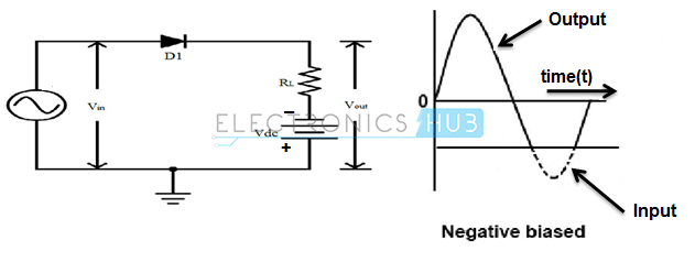
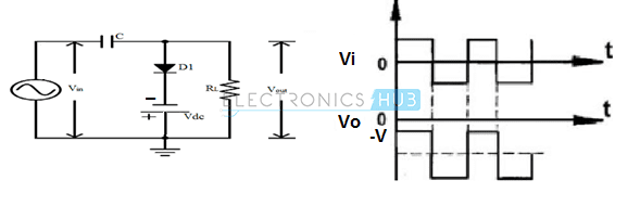
Series Negative Clipper with Positive Bias Voltage
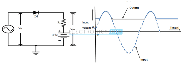
Positive Half Cycle: In this case the anode is connected to the positive supply and the cathode is maintained at positive bias potential.
- When Vin < Vd + Vdc, Output Voltage (VO) = Vdc Volts
- When Vin > Vd + Vdc, Output Voltage (VO) = (Vin – Vd) Volts
Negative Half Cycle: In this case the anode is connected to the negative supply and the cathode is maintained at positive bias potential.
- Output Voltage (VO) = + Vdc Volts
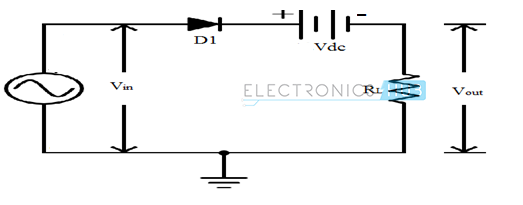
Series Negative Clipper with Positive Bias Voltage Connected in Series
Positive Half Cycle: Cathode is maintained at negative potential, anode observes a variable voltage. The diode is forward biased during the whole positive half cycle.
- When Vin < Vd + Vdc, Output Voltage (VO) = (Vin +Vdc – Vd) Volts
- When Vin > Vd + Vdc, Output voltage (VO) = 0 Volts
Negative Half Cycle: Cathode is maintained at negative potential and anode observes variable negative voltage.
- When Vin < Vdc – Vd, Output voltage (VO) = (Vin +Vdc –Vd) Volts
- When Vin > Vdc – Vd, Output voltage (VO) = 0 Volts
Series Negative Clipper with Negative Bias Voltage Connected in Parallel
Positive Half Cycle: In this circuit the anode is connected to the positive supply and the cathode is maintained at negative bias potential.
- When Vin < Vd + Vdc, Output Voltage (VO) = (Vin + Vd) Volts
- When Vin > Vd + Vdc, Output Voltage (VO) = + Vdc Volts
Negative Half Cycle: In this circuit the anode is connected to the negative supply and the cathode is maintained at negative bias potential.
- Output Voltage (VO) = (Vin + Vd) Volts
Series Negative Clipper with Negative Bias Voltage Connected in Series
Positive Half Cycle: Cathode is maintained at Vdc and anode observes a variable voltage.
- When Vin < Vd + Vdc, Output Voltage (VO) = 0 Volts
- When Vin > Vd + Vdc, Output voltage (VO) = (Vin –Vdc –Vd) Volts
Negative Half Cycle: Cathode is maintained at Vdc and anode observes a variable negative voltage. The diode will be reverse biased during the negative cycle.
- Output voltage (VO) = 0 Volts
Shunt Positive Clipper with Positive Shunt Bias Voltage
Positive Half Cycle: In this circuit, anode is connected to the positive supply and the cathode is maintained at positive bias potential.
- When Vin < Vd + Vdc, Output Voltage (VO) = Vin Volts
- When Vin > Vd + Vdc, Output Voltage (VO) = (Vd + Vdc) Volts
Negative Half Cycle: In this circuit, anode is connected to the negative supply and the cathode is maintained at positive bias potential.
- Output voltage (VO) = Vin Volts
Shunt Positive Clipper with Negative Shunt Bias Voltage
Positive Half Cycle: In this circuit, anode node is connected to the positive supply and the cathode is maintained at negative bias potential.
- Output voltage (VO) = (-Vdc + Vd) Volts
Negative Half Cycle: In this circuit, anode is connected to the negative supply and the cathode is maintained at negative bias potential.
- When Vin < Vdc, Output voltage (VO) = (-Vdc + Vd) Volts
- When Vin > Vdc, Output voltage (VO) = Vin Volts
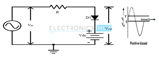
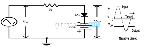
Shunt Negative Clipper with Positive Bias Voltage
Positive Half Cycle: Cathode is connected to the positive supply and the anode is maintained at positive bias potential.
- When Vin < Vdc – Vd, Output voltage (VO) = (Vdc – Vd) Volts
- When Vin > Vdc – Vd, Output voltage (VO) = Vin Volts
Negative Half Cycle: Cathode is connected to the negative supply and anode is maintained at positive bias potential.
- Output voltage (VO) = (Vdc – Vd) Volts
Clipping Both Half Wave Cycles
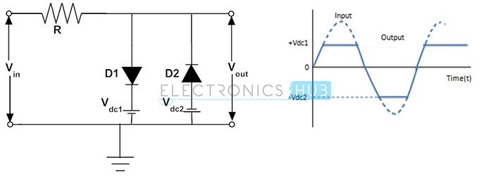
Positive Half Cycle: In this cycle, cathode of first diode D1 is maintained at +Vdc1 and its anode observes a variable positive voltage. Similarly anode of diode D2 is maintained at -Vdc2 and its cathode observes a variable positive voltage. The diode D2 will be completely reverse biased during the whole positive half cycle.
- When Vin < Vdc1 + Vd1 – Diodes D1 &D2 are reverse biased, Output voltage (VO) = Vin Volts.
- When Vin > Vdc1 + Vd1 – Diode D1 will be forward biased and D2 will be reverse biased, Output voltage (VO) = (Vdc1 + Vd1) Volts
Negative Half Cycle: In this cycle, cathode of diode D1 is maintained at +Vdc1 and its anode observes a variable negative voltage. Similarly anode of diode D2 is maintained at -Vdc2 and its cathode observes a variable negative voltage. The diode D1 will be completely reverse biased during the whole negative half cycle.
- When Vin < Vdc2 + Vd2 – Diodes D1 &D2 are reverse biased, Output voltage (VO) = Vin Volts.
- When Vin > Vdc2 + Vd2 – Diode D2 will be forward biased and D1 will be reverse biased, Output voltage (VO) = (-Vdc2 – Vd2) Volts
In this two side clipping circuit, both the positive and negative clipping levels can be varied independently. This type of circuit is called as Parallel based Clipper. It uses two diodes and two voltage sources connected in opposite directions.
Diode Clampers
Clampers can also be referred as DC restorers. Clamping circuits are designed to shift the input waveform either above or below a DC reference level without altering the shape of the waveform. This shifting of the waveform results in a change in the DC average voltage of the input waveform. The levels of peaks in the signal can be shifted using the clamper circuit, hence clampers can also be referred as level shifters.
Clampers can be broadly classified into two types. They are:
- Positive Clampers
- Negative Clampers
Positive Clamper: This type of clamping circuit shifts the input waveform in a positive direction, as a result the waveform lies above a DC reference voltage.
Negative Clamper: This type of clamping circuit shifts the input waveform in a negative direction, as a result the waveform lies below a DC reference voltage.
The direction of the diode in the clamping circuit determines the type of clamper circuit. The operation of a clamping circuit is mainly based on the switching time constants of a capacitor, which charges through the diode and discharges through the load.
Types of Clamper Circuits
Positive Clamper
The circuit of a Positive Clamper is shown in the following circuit. Here, the circuit consists of three main elements:
- Capacitor
- Diode
- Load
The diode is connected in parallel to the load in such a way that the cathode of the diode is connected to the capacitor and anode to the ground.
Let us analyze the circuit starting with a negative cycle after startup. During the first negative cycle, the diode is forward biased and acts as a closed switch. As a result, the capacitor charges to the peak input voltage, which we will call as VC.
In the next positive and negative cycles, the capacitor doesn’t lose much charge due to the RC Time Constant. As a result, the diode pretty much stays reverse biased.
Hence, the output voltage is the sum of applied input voltage and the charge stored at capacitor.
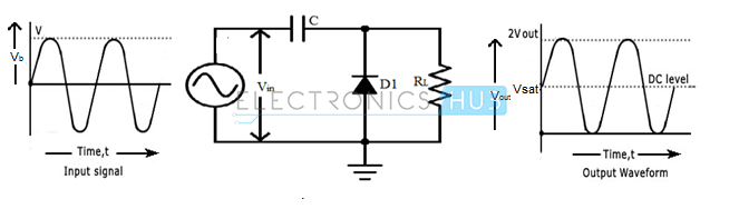
VOUT = VIN + VC
where VC is the peak of the input voltage.
From the above equation, it is clear that the above circuit adds a positive DC Shift to the input voltage.
Positive Clamper with Positive Reference Voltage
A positive reference voltage is connected in series with the diode in the positive clamper circuit such that the positive terminal of the reference voltage is connected in series with the anode of the diode. The operation is similar to the above circuit except that the capacitor charges to peak of the input voltage plus the DC Voltage.
If VP is the peak voltage and VDC is the DC Reference, then the capacitor voltage VC is VP + VDC and output voltage VOUT is VIN + VC.
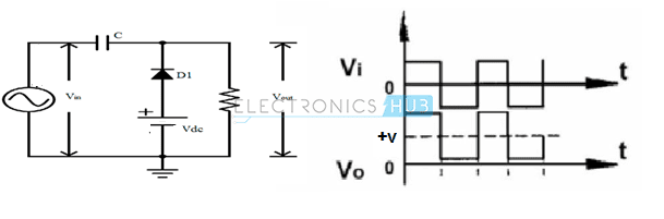
Positive Clamper with Negative Reference Voltage
During the negative half cycle, the diode starts conducting and the capacitor charges to VP – VDC.
During the consecutive positive and negative half cycles of the input waveform, the diode pretty much does not conduct and as a result, the output is equal to sum of voltage stored in the capacitor and applied input voltage.
As VC = VP – VDC, the output voltage is VIN + VC = VIN + (VP – VDC). The shift is still positive but less than the peak by VDC.
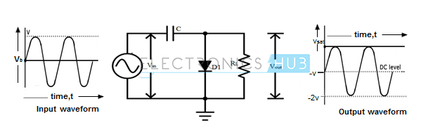
Negative Clamper
The Negative Clamping circuit consists of a diode connected in parallel with the load. The capacitor used in the clamping circuit can be chosen such that it must charge very quickly and it should not discharge very drastically. The anode of the diode is connected to the capacitor and cathode to the ground.
During the first positive half cycle of the input, the diode is in forward bias and as the diode conducts the capacitor charges very quickly to the peak of the input VP.
During the subsequent negative and positive half cycles of the input, the diode will be in reverse bias and the diode will not conduct. The output voltage will be equal to the sum of the applied input voltage and the charge stored in the capacitor. The output waveform is same as input waveform, but shifted below 0 volts by VP.
Negative Clamper with Positive Reference Voltage
The circuit arrangement is very similar to the Negative clamper circuit, but a DC reference supply is connected in series with the diode. The output waveform is also similar to the Negative clamper output waveform, but it is shifted towards the positive direction by an amount equal to the reference voltage at the diode.

Negative Clamper with Negative Reference Voltage
If the reference voltage directions in the above case are reversed and connected to the diode in series, then during the positive half cycle the diode starts conducting current before applying input voltage. Since the cathode has a very small negative reference voltage less than zero volts, the waveform is shifted away from the 0 volts towards the negative direction by an amount of the reference voltage.
Applications of Clippers
- Used for generating new waveforms and/or shaping the existing older waveforms.
- Clippers can be used as freewheeling diodes in protecting the transistors from transient effects by connecting the diodes in parallel with the inductive load.
- Commonly used in power supplies.
- In the separation of synchronizing signals existing from the composite color picture signals.
- Frequently used in FM transmitters for removing the excess ripples in the signals above a certain noise level.
Applications of Clampers
- Clampers can be frequently used in removing the distortions and identification of polarity of the circuits.
- For improving the reverse recovery time, clampers are used.
- Clamping circuits can be used as voltage doublers and for modelling the existing waveforms to a required shape and range.
- Clampers are widely used in test equipment and other sonar systems.

2 Responses
make all information about topic in slide form
So awesome, your notices are clearly summarised …….