In this diodes tutorial, we will see some of the common applications of diodes. As a simplest semiconductor component, diode has a wide variety of applications in modern electronic systems. Various electronic and electrical circuits use this component as an essential device to produce the required outcome.
Overview of Diode
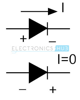
We know that a Diode allows the current flow only in one direction and hence it acts as a one-way switch. Diode is made of P and N type materials and has two terminals namely anode and cathode. This device can be operated by controlling the voltage applied to these terminals.
When the voltage applied to the anode is positive with respect to the cathode, the diode is said to be in Forward Bias. If the voltage applied to the diode is greater than the threshold level (generally, it is of ≈0.6V for Silicon Diodes), then diode acts as a short circuit and allows the current flow.
If the polarity of the voltage is changed i.e., the cathode is made positive with respect to anode, then it is said to be in Reverse Bias and acts as open circuit. As a result, no current flows through it.
The application areas of diodes include communication systems as limiters, clippers, gates; computer systems as logic gates, clampers; power supply systems as rectifiers and inverters; television systems as phase detectors, limiters, clampers; radar circuits as gain control circuits, parameter amplifiers, etc. The following description describes the various applications of diodes briefly.
Some Common Applications of Diodes
Before taking a look at various applications of diodes, let us quickly take a peek at a small list of common applications of diodes.
- Rectifiers
- Clipper Circuits
- Clamping Circuits
- Reverse Current Protection Circuits
- In Logic Gates
- Voltage Multipliers
and many more. Now let us understand each of these applications of diodes in more detail.
Diode as a Rectifier
The most common and important application of a diode is the rectification of AC power to DC power. Using diodes, we can construct different types of rectifier circuits. The basic types of these rectifier circuits are half wave, full wave center tapped and full bridge rectifiers. A single or combination of four diodes is used in most of the power conversion applications. Below figure shows diode operation in a rectifier.
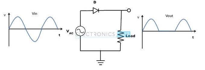
- During the positive half cycle of the input supply, anode is made positive with respect to cathode. So, the diode gets forward biased. This results in the current to flow to the load. Since the load is resistive, the voltage across the load resistor will be same as the supply voltage i.e., the input sinusoidal voltage will appear at the load (only the positive cycle). And the load current flow is proportional to the voltage applied.
- During the negative half-cycle of the input sinusoidal wave, anode is made negative with respect to cathode. So, the diode gets reverse biased. Hence, no current flows to the load. The circuit becomes open circuit and no voltage appears across the load.
- Both voltage and current at the load side are of one polarity means the output voltage is pulsating DC. Often, this rectification circuit has a capacitor that is connected across the load to produce steady and continuous DC currents without any ripples.
Diodes in Clipping Circuits
Clipping Circuits are used in FM transmitters, where noise peaks are limited to a particular value so that excessive peaks are removed from them. The clipper circuit is used to put off the voltage beyond the preset value without disturbing the remaining part of the input waveform.
Based on the diode configuration in the circuit, these clippers are divided into two types:
- Series Clipper
- Shunt Clipper
Further, these are again classified into different types.
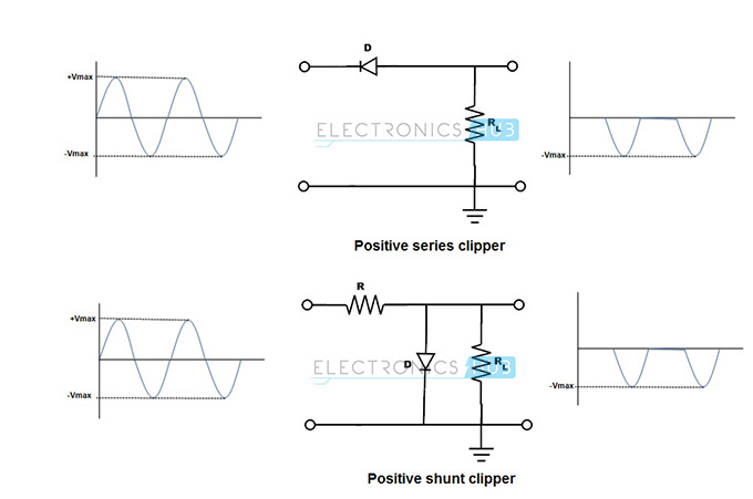
The above figure shows the positive series and shunt clippers. And using these clipper circuits, positive half cycles of the input voltage waveform will be removed. In positive series clipper, during the positive cycle of the input, the diode is reverse-biased so the voltage at the output is zero.
Hence, the positive half-cycle is clipped off at the output. During the negative half cycle of the input, the diode is forward-biased and the negative half cycle appears across the output.
In positive shunt clipper, the diode is forward-biased during the positive half cycle so the output voltage is zero as diode acts as a closed switch. And during the negative half cycle, the diode is reverse-biased and acts as open switch so the full input voltage appears across the output. With the above two diode clippers positive half-cycle of the input is clipped at the output.
Diodes in Clamping Circuits
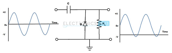
A clamper circuit is used to shift or alter either positive or negative peak of an input signal to a desired level. This circuit is also called as Level Shifter or DC restorer. These clamping circuits can be positive or negative depending on the diode configuration.
In positive clamping circuit, negative peaks are raised upwards so the negative peaks fall on the zero level. In case of the negative clamping circuit, positive peaks are clamped so that it pushes downwards such that the positive peaks fall on the zero level.
Look at the below diagram for understanding the diode application in clamping circuits. During the positive half-cycle of the input, diode is reverse-biased so the output voltage is equal to the sum of input voltage and capacitor voltage (considering the capacitor is initially charged). During the negative half-cycle of the input, diode is forward-biased and behaves as a closed switch so the capacitor charges to a peak value of the input signal.
Diodes in Logic Gates
Diodes can also perform digital logic operations. Low and high impedance states of logic switch are analogous to the forward and reverse-biased conditions of the diode respectively. Thus, the diode can perform logic operations such as AND, OR, etc. Although diode logic is an earlier method with some limitations, these are used in some applications. Most of the modern logic gates are MOSFET based.
The below figure shows the OR gate logic implemented using a pair of diodes and a resistor.
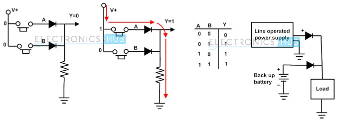
In the above circuit, input voltage is applied at V and by controlling the switches we get the OR logic at the output. Here logic 1 means high voltage and logic 0 means zero voltage. When both switches are in open state, both the diodes are in reverse-biased condition and hence the voltage at the output Y is zero. When any one of the switches is closed, the diode becomes forward-bias and as a result the output is high.
Diodes in Voltage Multiplier Circuits
Voltage multiplier consist of two or more diode rectifier circuits, which are cascaded to produce a DC output voltage equal to the multiple of the applied input voltage. These multiplier circuits are of different types like voltage doubler, tripler, quadrupler, etc. By the usage of diodes in combination with capacitors, we get the odd or even multiple of the input peak voltage at the output.

Above figure shows a half-wave voltage doubler circuit whose DC output voltage is twice that of peak input AC voltage. During the positive half-cycle of the AC input, diode D1 is forward-biased and D2 is reverse-biased. So, the capacitor C1 charges up to peak voltage Vm of the input through the diode D1. During the negative half-cycle of the AC input, D1 is reverse-biased and D2 is forward-biased. So, capacitor C2 starts charging thorough D2 and C1. Thus, the total voltage across the C2 is equal to the 2Vm.
During next positive half-cycle, the diode D2 is reverse-biased so the capacitor C2 will discharge through the load. Likewise, by cascading the rectifier circuits we will get the multiple values of input voltage at the output.
Diodes in Reverse Polarity Protection
The reverse polarity or current protection is necessary to avoid the damage that occurs due to connecting the battery in a wrong way or reversing the polarities of the DC supply. This accidental connection of supply causes to flow a large amount current thorough the circuit components, which might result in their failure or in a worst case, their explosion.
Therefore, a protective or blocking diode is connected in series with the positive side of the input to avoid the reverse connection problem.
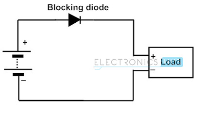
Above figure shows the reverse current protection circuit, where diode is connected in series with the load at the positive side of the battery supply. In case of the correct polarity connection, diode gets forward-biased and load current flows through it. But, in case of wrong connection, the diode is reverse-biased and that doesn’t allow any current to flow to the load. Hence, the load is protected against the reverse polarity.
Diodes in Voltage Spike Suppression
In case of an inductor or inductive loads, sudden removal of supply source produces a higher voltage due to its stored magnetic field energy. These unexpected spikes in the voltage can cause the considerable damage to the rest of the circuit components.
Hence, a diode is connected across the inductor or inductive loads to limit the large voltage spikes. These diodes are also called by different names in different circuits such as Snubber diode, Flyback diode, Suppression diode, Freewheeling diode and so on.
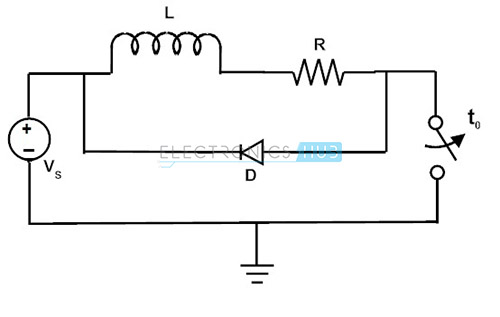
In the above figure, the freewheeling diode is connected across the inductive load for suppressing of voltage spikes in the inductor. When the switch is suddenly opened, a voltage spike is created in the inductor. Therefore, the freewheeling diode makes a safe path for the flow of current to discharge the voltage offered by the spike.
Diodes in Solar Panels
The diodes which are used for protection of solar panels are called as bypass diodes. If the solar panel is faulty or damaged or shaded by fallen leaves, snow and other obstructions, the overall output power decreases and arise hot spot damage because the current of the rest of the cells must flow through this faulty or shaded cell and causes overheating. The main function of the bypass diode is to protect the solar cells against this hot spot heating problem.
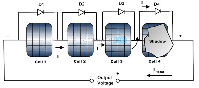
The above figure shows the connection of bypass diodes in solar cells. These diodes are connected in parallel with the solar cells thereby, limiting the voltage across the bad solar cell and allows the current from good solar cells to the external circuit. Thus, reduces the overheating problem by limiting the current flow through the bad solar cell.
Conclusion
We have some of the important Applications of Diodes. These include Rectifiers, Clippers, Clampers, Voltage Multipliers, Logic Gates, Solar Panels, Reverse Polarity Protection and Voltage Spike Suppression.

11 Responses
thx a lot
thanks this helps a lot
It was short and crispy…
Thank you very much for the helpful side.
Good.i like it.
this is very useful website with honest information
Thanks a lot, it really helped me
And you have a very good explanation and presentation process there…..thanks
Very good contribution.
Very good presentation
It was very helpful
Thanks a lot, it really helped me
And you have a very good explanation and presentation process there…..thanks