A capacitor has large number of specifications and characteristics. By observing the information printed on the body of a capacitor, we can understand very well about the characteristics of a capacitor. But some capacitors have colors or numeric codes on their body, due to this it is difficult to understand about characteristics. Each type or family of capacitor has its own set of characteristics and identification system. Some capacitors identification systems are easy to understand their characteristics and others use misleading symbols, letters and colors.
To understand the characteristics of a particular capacitor easily, first find out the capacitor family whether it is ceramic, plastic, film or electrolytic and from that it is easy to identify the characteristics. Even though capacitors have same capacitance value they may have different working voltages. If you use a capacitor which has low working voltage in place of a capacitor which has high working voltage then the increased voltage may damage the low voltage capacitor even though both capacitors have same capacitance.
Already we know that electrolytic capacitor has polarities, so while connecting the electrolytic capacitor in the circuit, positive terminal must connect to the positive connection and negative terminal of capacitor to negative connection otherwise the capacitor may damage. So it is always better to replace the damaged or old capacitor in the circuit with the new one which has same characteristics. The figure below figure shows the characteristics of a capacitor.
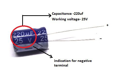
Figure 1.Capacitor Characteristics
Capacitor Characteristics
A capacitor comes with a set of characteristics. All these characteristics can be found in datasheets that are provided by capacitor manufacturers. Now let us discuss some of them.
Nominal Capacitance (C)
One of the most important one among all capacitor characteristics is the nominal capacitance (C) of a capacitor. This nominal capacitance value is generally measured in pico-farads (pF), nano-farads (nF) or micro-farads (uF), and this value is indicated with colors, numbers or letters on the body of a capacitor. This nominal capacitance value, which is printed on the side of a capacitor body, is not necessary to equal to its actual value.
The nominal capacitance value may change with working temperatures and with the circuit frequency. These nominal values are as low as one pico-farad (1pF) for smaller ceramic capacitors and as high as one farad (1F) for electrolytic capacitors. All capacitors have a tolerance rating that ranges from -20% to +80%.
Working Voltage (WV)
The working voltage is one more important characteristic of all capacitor characteristics. The maximum amount of voltage which is applied to a capacitor without failure during its working life is called as working voltage (WV). This working voltage is expressed in terms of DC and also it is printed on the body of a capacitor.
Generally working voltage which is printed on the body of a capacitor , refers its DC voltage but not its AC voltage , because the AC voltage is in its rms value. So capacitor working voltage must be greater than the 1.414 (Vm = Vrms x√2) times of its actual AC value to apply AC voltage to the capacitor. This specified DC working voltage of a capacitor(WV-DC) is valid only within in a certain temperature range, such as -300C to +700C. If you apply a DC or AC voltage which is greater than the working voltage of a capacitor then the capacitor may damage.
The working voltages which are commonly printed on the body of a capacitor are 10V, 16V,25V, 35V, 50V, 63V, 100V, 160V, 250V, 400V and also 1000V. All the capacitors will have a longer working life if they operated within their rated voltage values and in a cool environment.
Tolerance (±%)
Tolerance is the permissible relative deviation of the capacitance from the rated value, which is expressed in per cent. Like resistors, the tolerance value for capacitor also exists in either plus or minus values. This tolerance value is generally measured in either pico-farads (+/-pF) for low value capacitors which are less than 100pF or in percentages (+/-%) for higher value capacitors, which are greater than 100pF.
The tolerance value of a capacitor is measured at a temperature of +20°C and it is valid only at the time of its delivery. If a capacitor may be used after a longer period of storage then the tolerance value will increase, but according to the standard specifications, this value will not exceed twice the value which is measured at the time of its delivery. The delivery tolerances usually for wound capacitors are +/-(1%,2.5%,5%,10%,20%). The very general tolerance values variation for capacitors is 5% or 10%, and this is rated as low as +/-1% for plastic capacitors.
Leakage Current (LC)
All dielectric materials which are used in the capacitors to separate the metal plates of capacitors are not perfect insulators. They allow the small amount of current, such as leakage current to flows through it. This effect is because of the high powerful electric field which is formed by the charge particles on the plates of a capacitor when supply voltage (V) is applied to it.
The leakage current of a capacitor is a small amount of DC current which is in nano-amps (nA). This is because of the flowing of electrons through the dielectric material or around its edges and also by discharging it overtime when the power supply removed.
Leakage current is defined as transferring of unwanted energy from one circuit to another circuit. One more definition is the leakage current is a current when ideal current of the circuit is zero. Capacitors leakage current is a considerable factor in amplifier coupling circuits and in power supply circuits.
The leakage current is very low in film or foil type capacitors and it is very high (5-20 uA per uF) in electrolytic (tantalum and aluminum) type capacitors, where their capacitance values are also high.
Working Temperature
The capacitance value of a capacitor varies with the changes in temperature which is surrounded the capacitor. Because the changes in temperature, causes to change in the properties of the dielectric. Working Temperature is the temperature of a capacitor which operates with nominal voltage ratings. The general working temperatures range for most capacitors is -30°C to +125°C. In plastic type capacitors this temperature value is not more than +700C.
The capacitance value of a capacitor may change, if air or the surrounding temperature of a capacitor is too cool or too hot. These changes in temperature will cause to affect the actual circuit operation and also damage the other components in that circuit. I think it is not a simple thing to keep the temperatures stable to avoid capacitors from frying.
The liquids within the dielectric can be lost to evaporation especially in electrolytic capacitors (aluminum electrolytic capacitors) when they will operate at high temperatures (over +850C)and also the body of the capacitor would become damaged due to the leakage current and internal pressure. And also the electrolytic capacitors cannot be used at low temperatures, such as below -100C.
Temperature Coefficient
The temperature coefficient (TC) of a capacitor describes the maximum change in the capacitance value with a specified temperature range. Generally the capacitance value which is printed on the body of a capacitor is measured with the reference of temperature 250C and also the TC of a capacitor which is mentioned in the datasheet must be considered for the applications which are operated below or above this temperature. Generally the temperature coefficient is expressed in the units of parts per million per degree centigrade (PPM/0C) or as a percent change with a particular range of temperatures.
Some capacitors are linear (class 1 capacitors), these are highly stable with temperatures; such capacitors have a zero temperature coefficient. Generally Mica or Polyester capacitors are examples for the Class 1 capacitors. TC specification for class 1 capacitors will always specifies the capacitance change in parts per million (PPM) per degrees centigrade.
Some capacitors are non linear (class 2 capacitors), these capacitors temperatures are not stable like class1 capacitors, and their capacitance values will increase by increasing the temperature values, Hence these capacitors gives a positive temperature coefficient. The main advantage of the class 2 capacitors is their volumetric efficiency. These capacitors are mainly used in the applications where high capacitance values are required, while stability and quality factor with temperatures are not main factors to consider. The Temperature Coefficient (TC) of class 2 capacitors is expressed directly in percentage. One of the useful applications of temperature coefficient of capacitors is to use them to cancel out the effect of temperature on other components within a circuit such as resistors or inductors etc.
Polarization
Generally the capacitor polarization belongs to the electrolytic type capacitors, such as aluminum type and tantalum type of capacitors. Majority of the electrolytic capacitors are polarized, that is it needs correct polarity when supply voltage is connecting to the capacitor terminals, such as positive (+ve) terminal to positive (+ve) connection and negative (-ve) to negative (-ve) connection.
The oxide layer inside the capacitor may broken by incorrect polarization, this causes to flow of high currents through the device. As a result capacitor damages as mentioned earlier. To prevent incorrect polarization the majority of electrolytic capacitors have arrows or black stripe or band or chevrons on one side of their body to denote their negative (-ve) terminals as shown in the below figure.
Polarized capacitors have large leakage currents if their supply voltage is inverted. The leakage current in polarized capacitors distort the signal, over heats the capacitor and finally destroys. The basic reason to use polarized capacitors is their less cost than non-polarized capacitors of same voltage ratings and same capacitance values. Basically the polarized capacitors are available in the units of micro-farads, such as 1uF, 10uF etc.
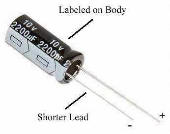
Figure 2.Polarization of the Capacitor
Equivalent Series Resistance (ESR)
The equivalent series resistance (ESR) of a capacitor is defined as the AC impedance of a capacitor when it used at very high frequencies and also with the consideration of dielectric resistance. Both the DC resistance of dielectric and the capacitor plate’s resistance are measured at a particular temperatures and frequency.
ESR acts like a resistor in series with a capacitor. The ESR of a capacitor is the rating of its quality. We know that theoretically a perfect capacitor is lossless and also have the ESR value zero. Often this resistance (ESR)causes to failures in the capacitor circuits.
The Effects of Equivalent Series Resistance
The equivalent series resistance (ESR) of the output capacitor in the circuit causes to affect the performance of the device. And also the ESR may reduce the supply voltage of a capacitor. The ESR is quite opposite to the insulation resistance of a capacitor which is presented as pure resistance in parallel with the capacitor in some type of capacitors. An ideal capacitor has only its capacitance and ESR value is very less (less than 0.1Ω).
If the dielectric thickness increases then the ESR will increase. If the surface area of the plate increases then the ESR value will go down. To calculate capacitor’s ESR, we requires something other than a standard capacitor meter such as ESR meter. If the capacitor meter is a handy device then it will not detect capacitor failures which increase the ESR value.
In a non-electrolytic capacitor or a capacitor with solid electrolyte the metallic resistance of leads, electrodes and losses in the dielectric are causes to ESR. Generally the ESR values for ceramic capacitors are in between 0.01 to0.1 ohms. Aluminum and tantalum electrolytic capacitors with non solid electrolyte have very high ESR values, such as several ohms. A main problem with aluminum electrolytic capacitors is that, the circuit components will damage if the ESR values of the capacitors which are used in that circuit increases over time in the operation.
Generally the ESR values are less for polymer capacitors than electrolytic (wet) capacitors of same value. Thus the polymer capacitors can handle the higher ripple currents. A capacitor can be used as a filter which having a very low ESR ratings. Capacitors have the ability of storing the electrical charge even though the charging current is not flowing through it. The capacitors used in the televisions, photo flashes and capacitor banks are generally of electrolytic type capacitors. According to the thumb rule the leads of large value capacitors are need to never touch after power supply was removed.

3 Responses
This improved my understanding of capacitors. This is what exactly im looking for. Awesome tutorial.
That’s Greatful Keep up!!!!
How to find the nominal capacitance of capacitor if letters and number is given ??