The circuit presented here is used to change the tune/melody into a different pitch level by devoid of loss in the tune. The characteristics of the signal might be varied at different moment of time. The melody which is produced by melody generator IC can be postponed and the pitch of the tune mottled at different instance of time. This can generate different musical sounds from a single melody.
Also read the post: Simple Audio Tone Control Circuit
The word ‘modulation’ is used to denote change of the tune by generating delay along with other effects.
Circuit Diagram of Audio Equalizer Circuit:
Components Used in this Circuit:
- IC
- IC1, IC2(4046) – 2
- IC3(NE555) – 1
- IC4(CD4051) – 1
- ResistorC1,C2(4.7uf) – 2
- R1,R3(2.2K) – 2
- R2,R4(220K) – 2
- R5,R6(10K) – 2
- R7(56K) – 1
- VR1(10K) – 1
- VR2(5K) – 1
- C3(470uf) – 1
- C4(.1uf) – 1
- D1(1N4148) – 1
- T1(SL100) – 1
- UM66 – 1
- Speaker – 1
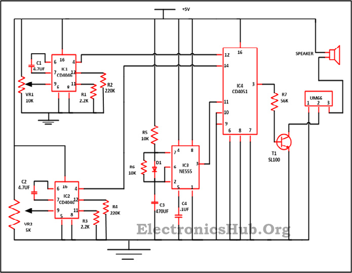
Components Description:
1. Phase Locked Loop (for Voltage Controlled Oscillator):
IC for the Phase Locked Loop is linked with 220K ohm (R2 ae well as R4) at pin number 12.The offsets are mainly provided by these resistors. Large value of R2 or R4 implies that there is a merely a minute offset.To shun total silence at the time input is 0V, R2 resistor offsets the range of frequency.
The frequency at output from VCO(pin4) at the time when voltage at pin 9 is half the voltage given is calculated by
f=1/ (R1*C1) = 1/ (2.2K*4.7u) = 96.71 Hz.
The frequency alter with the variation of the voltage at VCO’s input is altered by potentiometer.
2. 555 Timer: This IC works like a astable multivibrator.
The on-time is = R5+C3=10Kohm*470pF=47msec
Off-time is also equal to 4.7 m sec (R6*C3)
The diode is connected to restrict the path during off-time while discharging the capacitor.The main thinking is to have the similar on and off times(50% of the duty cycle). To remove any noise presented in the circuit then C4 of 0.1uF is used.It is not compulsory to be connected.
555 timer output is worked as a selection line for the multiplexer, both the outputs of VCO is multiplexes by it.
3.Multiplexer: CD4051 is worked as 2.1 multiplexer, with both the ouput of VCO’s worked as inputs for pin 13 and 14 of MUX and a line for selection is used to select output from each of these from PLL having same time period. By concluding few additional VCO’s variety of effects can be inserted to the audio and multiplexing them and the speaker get it as an output. Lots of varieties of UM66T are available in the market which produces tone of various songs. For example ‘Jingle bells’, we wish you a merry X’mas and ‘santa Clause is coming to town produced by the UM66T01. To alter the melodies any melody can be used in the place of UM66 in the circuit above.
Working of Audio Equalizer Circuit:
IC UM66 is used in the circuit to alter the melody which is produced by the melody generator. Oscillation is generated by the voltage controlled oscillator at the time when constant voltage is applied. For the purpose of the VCOs phase locked loop IC (i.e. 4046) which is IC1 and IC2 in the circuit is used. PLL chip comprises of VCO as well as Phase comparator.
Related Post: Multi Channel Audio Mixer Circuit
By the help of the potentiometer, the voltage which is given to VCOs can be changed. To modify the VCO input voltage potentiometer of value 5K and 10K are attached in the circuit. This voltage is taken by IC1 and IC2. The output of VCOs at the pin 4 of IC CD4046 is a time-multiplexed by a CD4051 multiplexer IC (which IC 4 in the circuit diagram).
The signal which is selected for the multiplexer is produced by 555 timer(IC3) which is working as a astable multivibrator. 4.7 is the time taken by the each high as well as low pulse which is upcoming from 555 timer. The duty cycle is produce surely to be 50% by bringing a IN4148 a small signal diode. The output is then applied to the NPN transistor at the base terminal by a 40K ohm resistor.
The input for melody generator UM66 (Various other IC for the purpose of melody generation can also be used) is taken from the collector terminal. The output of the melody generator is then supplied at one terminal of the 4 ohm speaker(SP) and the left terminal of the speaker is linked with 5 volt power supply.
With the minute alterations in the locations of the potentiometer, the same tune can listen to the many distinct tones, height as well as pitch. In the same manner variety of melodies can be changed by just putting that particular melody IC at the place of UM66 in the above circuit.
