Audio tone control circuits are mainly used for 2 reasons. The first reason is to control the BANDWIDTH of the signal, which is entering into the audio POWER amplifier. It may not possible to recollect the original signal at the speaker if the bandwidth is not limited. The second reason is to satisfy with the music. Tone controlling is nothing but controlling the frequency of the signal to be amplified by the audio power amplifier. Normal audio signal consists of mixed frequency. Low frequencies in audio signals are called as BASS and higher frequencies are named as TREBLE. If you think about separating the frequencies in audio signal then Audio tone control circuit comes on to the picture.
Basically there are 2 types of audio tone control circuits. First one is active tone control circuit and other is passive tone control circuit. An Audio tone control circuit is said to be active if it consists of amplifier. In absence of amplifier, circuit is said to be passive tone control circuit.
Also Get an Idea About How a Subwoofer amplifier circuit works?
This article explains you how to design an audio tone control circuit with the gain of around 25. This design needs less number of components and it is cost effective.
Audio Tone Control Circuit Diagram:
Circuit Components:
- TL072 Operational amplifier
- 100k Pot – 3
- Audio jack
- Resistors – 2.2M, 100k(2), 10k(2), 1k(2),
- Capacitors – 100pF, 1uF, 2.2uF, 22nF(2), 220nF, 2.2nF
Audio Tone Control Circuit Design:
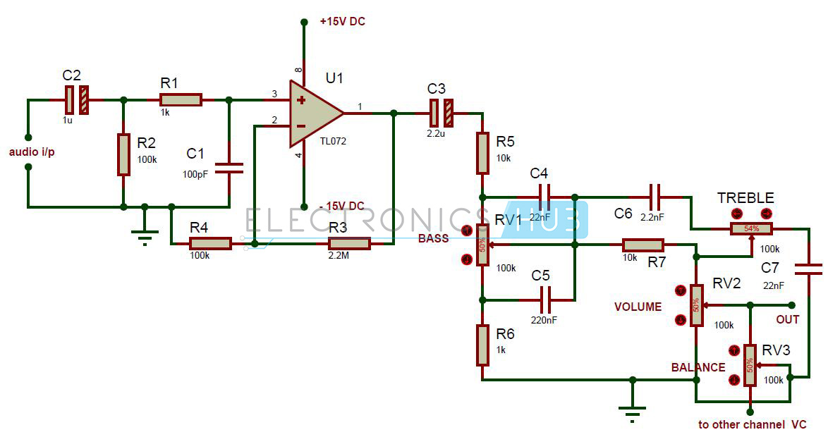
The audio tone control circuit mainly consists of two sections – one is amplifier and other is passive tone control circuit.
Amplifier Stage:
The amplifier stage consists of TL072 non inverting amplifier. Resistor R3 is connected in between the pins 1 and 2 to provide the feedback to the operational amplifier. Pin2 of op amp is connected to the ground through the resistor R4. Here resistors R3 and R4 are used to set the gain of the operational amplifier. The gain of operational amplifier in non inverting mode is given as
Av = 1+ (R3/R4).
The input impedance of first stage is approximately equal to the R3. Here C2 capacitor is used as a decoupling capacitor and also used to set the low frequency cut off. Here resistor R2 is used to reduce the offset effect on the operational amplifier output. The value of this resistor should be approximately equal to R3||R2.
Tone Control Circuit:
The tone control section can produce a boost of 20dB. In this section, pot RV1 used to the BASS and other pot is used to control the TREBLE. Pot RV2 is used to control the VOLUME AND Pot RV3 is used to adjust the balance. Resistor R7 provides the isolation between BASS and TREBLE.
Dual Power Supply Circuit Design:
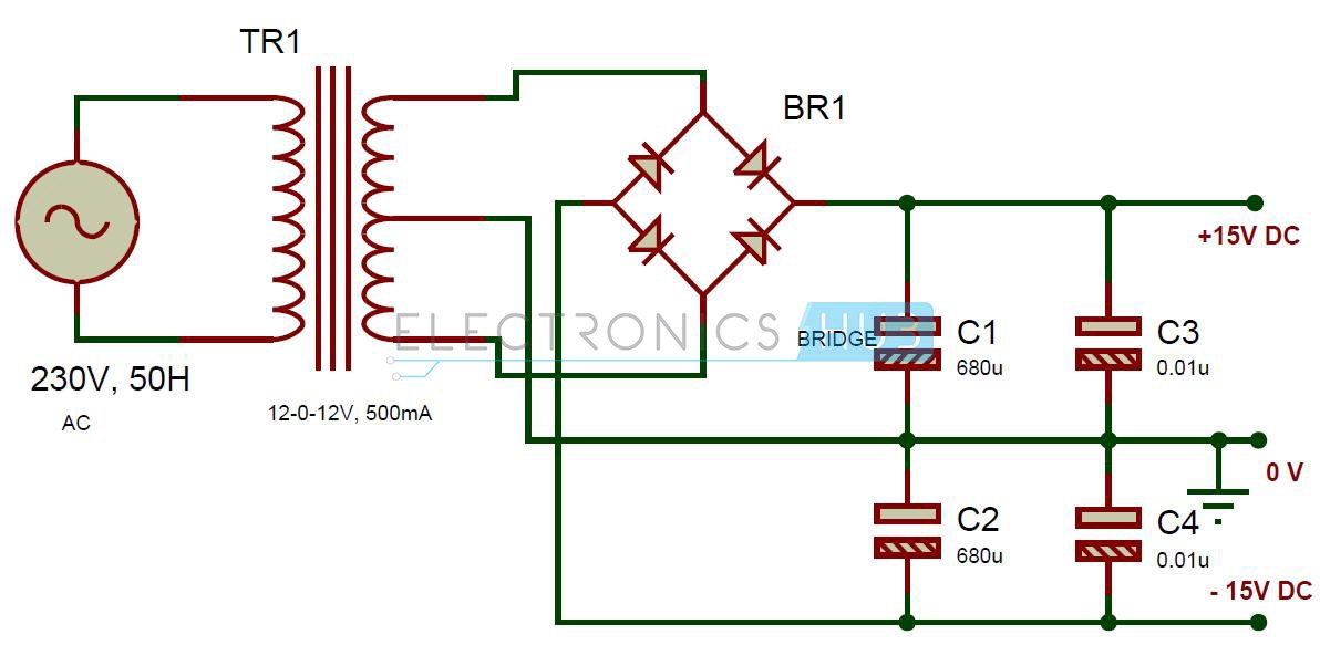
Circuit Components:
- 12-0-12V, 500mA center tapped transformer
- Diode bridge – 1A
- 680uF Electrolytic capacitors – 2
- 0.01uF capacitors – 2
This circuit provides +15V and -15V power supply to the audio tone control circuit. Here center tapped transformer is used to step down the voltage. Diode Bridge D1 is made with four 1n4007 diodes. This diode bridge is used to provide pulsating DC from AC voltage. Capacitors are used to filter the AC ripples.
Do you know How an Audio Equalizer Circuit Works using Combinational Logic Gates?
How to Operate Audio Tone Control Circuit:
- Give the connections as per the circuit diagram.
- While giving the connections, make sure that there is common connection between AC and DC.
- Provide +15V and -15V supply to the audio tone control circuit from Dual power supply circuit.
- Now apply the audio input to the circuit with the help of audio jack.
- You can vary the audio tone by varying the BASS or TREBLE.
- By varying the pot RV2 you can control the volume.
Audio Tone Control Circuit Advantages:
- The circuit uses less components and it is cost effective.
- The circuit is portable.
Audio Tone Control Circuit Applications:
- This audio tone control circuit is used in Audio systems to control the audio tone.
- Used in music players to control the bandwidth.
Audio Tone Control Circuit Limitations:
- This circuit is simulated in software and may require some changes in practical.

One Response
Can you say the changes to be made to work in practical?