The mains supply is an alternating current in the form of a sine wave. The common power supply to households is a single phase AC supply. The frequency and the amplitude of the AC wave vary from region to region with 50 Hz or 60 Hz being the common frequency and an amplitude of 110V or 240V.
The power rating of an electrical device or appliance will determine the power utilized by it to work properly. What if we desire to reduce the intensity of an electric bulb or run a motor at less speed? This can be achieved by limiting the power to the device i.e. supplying less power than the maximum rated power.
This concept of restriction on the power supplied to a device is known as AC power control. AC power control allows us to efficiently use the available power for various applications.
There are two types of AC power control: ON-OFF or pulse skipping modulation control and phase control. In on-off control, the load is connected to the AC supply for short interval of time and the AC supply is switched off for some interval.
A fast switching device like a thyristor is used to connect and disconnect the load to the AC power supply. In phase control method, the load is connected to the AC supply for a specific period of both the half cycles.
A PWM technique based AC power control is designed here which is a type of on-off control. The circuit regulates the AC power supplied to any load like an electric bulb, motor, amplifiers etc.
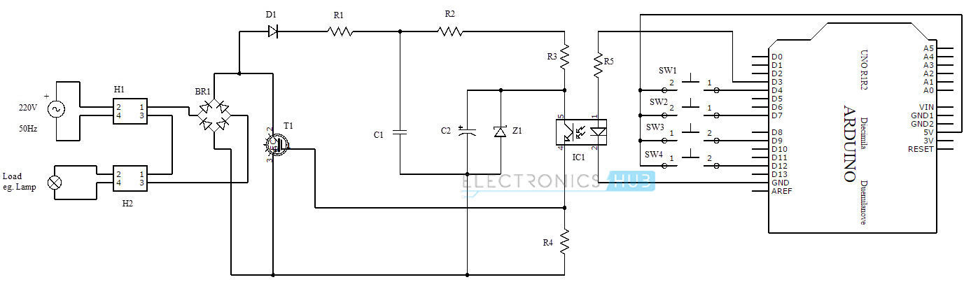
PWM Based AC Power Control using MOSFET / IGBT Circuit Diagram
Components
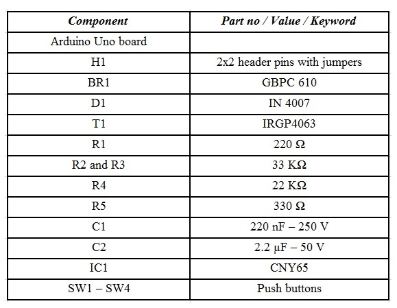
Component Description
Arduino Uno Board
It is a microcontroller based prototyping board. The purpose of Arduino board in this project is to generate the required PWM signal and also control the duty cycle of the PWM signal with the help of switches to control the output power delivered to the light bulb.
One of the digital I/O pins is used as a PWM output and four other digital I/O pins are used as inputs from switches.
GBPC 610
It is a bridge type full wave rectifier used in AC to DC conversion.
IRGP4063
It is an IGBT (Insulated Gate Bipolar Transistor) with a rating of 600V and 96A with a maximum power dissipation of 330W. The purpose of the IGBT in this circuit is to act as a switch for switching the supply on and off according to the duty cycle pf the PWM.
CNY65
It is an optocoupler IC which has a phototransistor which is optically coupled to an LED (infrared light is emitted). It is used to isolate the weak PWM signal circuit from the high voltage and high current transistor (IGBT or MOSFET).
Working
The aim of this circuit is to control the AC power supplied to an electrical device like a light bulb with the help of pulse width modulated AC sine wave. The AC power supply (240V @ 50Hz) is given to a bridge rectifier (BR1). This is further rectified with the help of diode D1 and the filter circuit formed by the resistor R1 and capacitor C1.
The output of this filtered signal is a DC signal, which is given to the optocoupler as DC voltage. A light bulb is connected in series with the bridge and the power supply.
An Arduino Uno board is used to generate the PWM wave. Four switches are used with the Arduino to select different duty cycles of PWM signal.
The four switches associated with the Arduino provide duty cycles of 0%, 25%, 50% and 75%. When no switch is pressed, maximum power is delivered to the light bulb.
The PWM signal from the microcontroller (Arduino) is given to the input of an Optocoupler (CNY65) with the transistor in the optocoupler connected to DC voltage from the rectifier for quick conduction.
A resistor (R5) is used in series with the optocoupler to protect the IR emitting diode in the optocoupler. Resistor R4 is used to reduce the switching spikes. The purpose of the optocoupler is to isolate the low voltage PWM signal from the large voltage and current in the transistor.
The output of the optocoupler is the same PWM signal from the microcontroller (Arduino) and will act as the input signal applied to the gate of the transistor.
The transistor must be a high speed switching device which can handle large power. Hence, a power MOSFET or IGBT can be used. The important thing to remember when operating with MOSFET and PWM is that the MOSFET stays on
How PWM can be used to control the AC power? The most effective way to control the AC power is to tune the frequency of the AC signal. Consider a situation where a switch is present between the electrical device like a bulb and the mains power supply.
If the switch is ON (or closed) for 2 seconds and OFF (or open) for 2 seconds, then the power consumption is reduced by 50%.
If the switching action is so fast that it is not detected by the human eye, then the light bulb will appear as it is continuously glowing with half the luminance and consuming only 50% power. An IGBT or a MOSFET is used as a switch and the switching action of the transistor is controlled by a pulse.
The on (high) and off (low) period of the pulse will determine whether the transistor is switched on or off and consequently controlling the AC power and this is how a PWM signal is used in AC power control.
The on and off periods of the PWM wave define a factor called Duty cycle and this is an important parameter in controlling the power.
A 50% duty cycle PWM wave will provide only 50% of the maximum power and a 33% duty cycle PWM will deliver only 33% of the maximum power.
An important thing to be considered when choosing the switching device is that it should have a fast switching action and also should be capable of handling large power.
Note
- The circuit mentioned here can be used with light bulbs. Inductive loads like motors cannot be used as the circuit is DC biased.
- Zero cross detection circuit can be used but this might keep the microcontroller very busy as it has to continuously monitor for zero crossing.
- MOSFETS can also be used in place of IGBT but MOSFETS the heat dissipation is better in case of IGBT.
- The position of the lamp can be moved and placed at the drain of the transistor.
- In case of any flickers, a 100µH inductor can be used in the output path.
Applications
- This circuit can be used to control the AC power supplied an electrical device.
- Slight modifications in the circuit will allow it to control AC power to inductive loads like motors.
- Can be used to save the AC power as it can regulate the power supplied to the electrical device.

12 Responses
Value of Zener diode , Z1?
can you provide the value of zener Z1?
Can u tell me the sender diod valu?
Good morning, I set up the project but would usalo with motor ac 230v, called with candescent lamp and it worked fine, but with engine it burns the igbt transistor, you speak at the end of the project with minor modifications for use with motor ac 230v ,thank you so much.
Hi, For inductive loads, we can use a Snubber Circuit. We haven’t tested it yet.
Can you provide arduino program used for this project?
thank you
What amendments would have to be made to allow the circuit to run a inductive load ?
Hi, A Snubber Circuit can be used with the inductive load. This is just a theory and we haven’t tested it yet. The selection of the components in the Snubber Circuit (R and C in case of a simple RC Snubber) plays an important role.
Hi,
What value should the Zener diode be?
Thanks
Can anyone send me the code for this project? Send here gaygabriellemecamay@gmail.com thanks
Too much effort, too expensive …
As optocoupler a MOC3021 then a resistor and a triac – ready – better and easier it does not work.