In this tutorial, we will learn about some of the commonly used SCR Protection techniques against over voltage, over current, di/dt, dv/dt, etc.
Introduction
For satisfactory and reliable operation, the specified ratings of an SCR should not be exceeded due to overload, voltage transients and other abnormal conditions. If the ratings are exceeded, there is a chance of damage permanently to the SCR. Due to the reverse recovery process during the turn OFF the SCR, the voltage overshoots occur in the SCR.
Also, during turn ON, switching action produces over voltages in the presence of inductance. In the event of a short circuit, a large current flows through the SCR which is very larger than the rated current. Therefore, to avoid the undesirable effects on the SCR due to these abnormal conditions, SCR must be provided with suitable protection circuits.
Some of the protection techniques employed for an SCR include over voltage protection, over current protection, dv/dt protection and di/dt protection. Also, to operate the SCR in permissible temperature limits, heat produced at the junctions must be dissipated. This can be accomplished by using heat sinks. Let us discuss in brief on these protection methods.
Overvoltage
Over voltages are the greatest causes of failure of SCRs. These transient over voltages often lead to unscheduled turn ON of the SCR. Also, may lead to the permanent destruction of the SCR if the reverse transient voltage is more than the VBR across the SCR.
There are several causes of appearing these over voltages like commutation , chopping , lightening , etc. Depends on these sources , over voltages are divided into two types internal and external over voltages.
Internal Overvoltages
Internal over voltages arise while the SCR is in operation. During the turn OFF of an SCR, a reverse current continues to flow through the SCR after the anode current decreased to zero to sweep away the earlier stored charge. This reverse current decay at a faster rate at the end of reverse recover interval.
Due to the inductance of the circuit, this high di/dt produces a high voltage. This voltage value may be much higher than the rated value of the SCR and hence the SCR may be damaged.
External Overvoltages
These voltages are arises from the supply source or load. Some of these are
- If SCRs are in blocking mode in a converter circuit which is supplied with transformer, a small magnetizing current flow through the primary of the transformer. If the primary side switch is suddenly removed, a high voltage transient is produced in the secondary of the transformer and hence it is applied across the SCR. This voltage is several times that of the break over voltage of the SCR.
- Lightning surges on the HVDC systems to which SCR converters are connected causes a very high magnitude of over voltages.
- If the SCR converter circuit is connected to a high inductive load, the sudden interruption of current generates a high voltage across the SCRs.
- If the switches are provided on DC side, a sudden operation of these switches produces arc voltages. This also gives rise the over voltage across the SCR.
Protection Against Over voltages
To protect the SCR against the transient over voltages, a parallel R-C snubber network is provided for each SCR in a converter circuit. This snubber network protects the SCR against internal over voltages that are caused during the reverse recovery process. After the SCR is turned OFF or commutated, the reverse recover current is diverted to the snubber circuit which consists of energy storing elements.
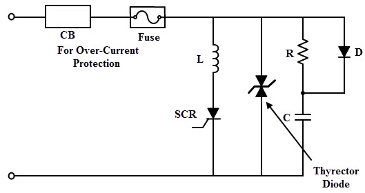
The lightning and switching surges at the input side may damage the converter or the transformer. And the effect of these voltages is minimised by using voltage clamping devices across the SCR. Therefore, voltage clamping devices like metal oxide varistors, selenium thyrector diodes and avalanche diode suppressors are most commonly employed.
These devices have falling resistance characteristics with an increase in voltage. Therefore, these devices provide a low resistance path across the SCR when a surge voltage appears across the device. The figure below shows the protection of SCR against over voltages using thyrector diode and snubber network.
Overcurrent
During the short circuit conditions, over current flows through the SCR. These short circuits are either internal or external. The internal short circuits are caused by the reasons like failure of SCRs to block forward or reverse voltages, misalignment of firing pulses, short circuit of converter output terminals due to fault in connecting cables or the load, etc. The external short circuits are caused by sustained overloads and short circuit in the load.
In the event of a short circuit, the fault current depends on the source impedance. If the source impedance is sufficient during the short circuit, then the fault current is limited below the multi-cycle surge rating of the SCR. In case of AC circuits, the fault occurs at the instant of peak voltages if the source resistance is neglected.
In case of DC circuits, fault current is limited by the source resistance. Therefore, the fault current is very large if the source impedance is very low. The rapid rise of this current increase the junction temperature and hence the SCR may get damaged. Hence the fault must be cleared before occurrence of its first peak in other words fault current must be interrupted before the current zero position.
Protection Against Overcurrent
The SCRs can be protected against the over currents using conventional over current protection devices like ordinary fuses (HRC fuse, rewirable fuse, semiconductor fuse, etc,), contractors, relays and circuit breakers. Generally for continuous overloads and surge currents of long duration, a circuit breaker is employed to protect the SCR due to its long tripping time.
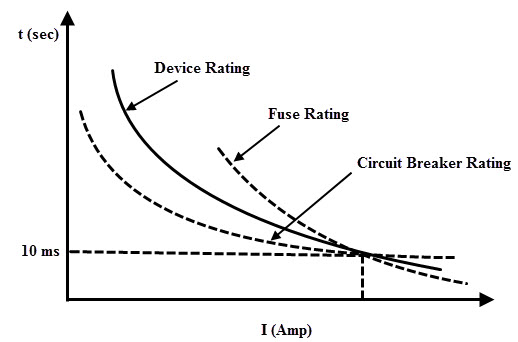
For an effective tripping of the circuit breaker, tripping time must be properly coordinated with SCR rating. Also, the large surge currents with short duration (are also called as sub-cycle surge currents) are limited by connecting the fast acting fuse in series with an SCR.
So the proper coordination of fusing time and the sub-cycle rating must be selected for a reliable protection against over currents. Therefore, the proper coordination of fuse and circuit breaker is essential with the rating of the SCR.
The selection of fuse for protecting the SCR must satisfy the following conditions.
- Fuse must be rated to carry the full load current continuously plus a marginal overload current for a small period.
- I2t rating of the fuse must be less than the I2t rating of the SCR
- During arcing period, fuse voltage must be high in order to force down the current value.
- After interrupting the current, fuse must withstand for any restricted voltage.
di/dt Protection of SCR
The anode current starts flowing through the SCR when it is turned ON by the application of gate signal. This anode current takes some finite time to spread across the junctions of an SCR. For a good working of SCR, this current must spread uniformly over the surface of the junction.
If the rate of rise of anode current (di/dt) is high results a non-uniform spreading of current over the junction. Due to the high current density, this further leads to form local hot spots near the gate-cathode junction. This effect may damage the SCR due to overheating. Hence, during turn ON process of SCR, the di/dt must be kept below the specified limits.
To prevent the high rate of change of current, an inductor is connected in series with thyristor. Typical SCR di/dt ratings are in range between 20- 500 ampere per microseconds.
dv/dt Protection of SCR
When the SCR is forward biased, junctions J1 and J3 forward biased and junction J2 is reverse biased. This reverse biased junction J2 exhibits the characteristics of a capacitor. Therefore, if the rate of forward voltage applied is very high across the SCR, charging current flows through the junction J2 is high enough to turn ON the SCR even without any gate signal.
This is called as dv/dt triggering of the SCR which is generally not employed as it is false triggering process. Hence, the rate of rise of anode to cathode voltage, dv/dt must be in specified limit to protect the SCR against false triggering. This can be achieved by using RC snubber network across the SCR.
Working of Snubber Circuit
As we discussed above, the protection against high voltage reverse recovery transients and dv/dt is achieved by using an RC snubber circuit. This snubber circuit consists of a series combination of capacitor and resistor which is connected across the SCR. This also consist an inductance in series with the SCR to prevent the high di/dt. The resistance value is of few hundred ohms. The snubber network used for the protection of SCR is shown below.

When the switch closed, a sudden voltage appears across the SCR which is bypassed to the RC network. This is because the capacitor acts as a short circuit which reduces the voltage across the SCR to zero. As the time increases, voltage across the capacitor builds up at slow rate such that dv/dt across the capacitor is too small to turn ON the SCR. Therefore, the dv/dt across the SCR and the capacitor is less than the maximum dv/dt rating of the SCR.
Normally, the capacitor is charged to a voltage equal the maximum supply voltage which is the forward blocking voltage of the SCR. If the SCR is turned ON, the capacitor starts discharging which causes a high current to flow through the SCR.
This produces a high di/dt that leads to damage the SCR. And hence, to limit the high di/dt and peak discharge current, a small resistance is placed in series with the capacitor as shown in above. These snubber circuits can also be connected to any switching circuit to limit the high surge or transient voltages.

2 Responses
very good material inside this website
How the protection of scr is one against di/dt and dv/dt