The sophisticated modern electrical grid gives us access to power almost everywhere and any time. It is hard to imagine life without electricity even for a single day.
There might be some situations like storms, floods, or disasters where there will be severe interruption in power supply.
It might take days for the supply companies to restore the power supply. For temporary interruption in power supply, we normally depend on inverters.
Inverters can be useful only for few hours. But for days of interruption in power supply, electrical generators come in handy.
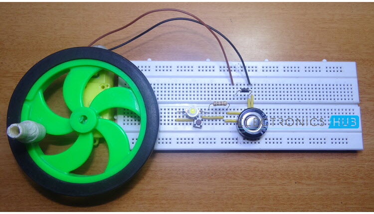
Small Electrical Generators are very useful for household or small industrial use in case of emergency situations. The aim of this article is to illustrate a do-it-yourself Hand Cranked Generator that can light up a high power LED.
There are battery powered LED torches but the battery can only last for few hours. With very simple hardware and construction process, a DIY hand crank generator can be used to generate small current that can be used for a very long time.
How To Design A Simple Hand Crank Generator?
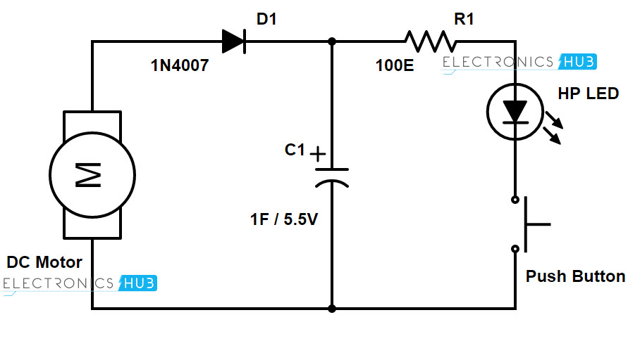
Circuit Diagram
 Hardware Required
- DC Motor
- Plastic Gears for Motor
- Wheel with crankshaft
- 1N4007
- 1F / 5.5V Super Capacitor
- High Power LED
- 100Ω Resistor
- Switch
Component Description
1F / 5.5V Capacitor
It is a super capacitor used in the project. Super capacitors are capacitors with high capacity. Generally, capacitance of 1F and higher are considered as super capacitors.

The 1F capacitor used here is a button type super capacitor that is generally used as a PCB mounting capacitor. Some of the common applications of 1F super capacitor are memory back up, battery backup and as alternative to batteries.
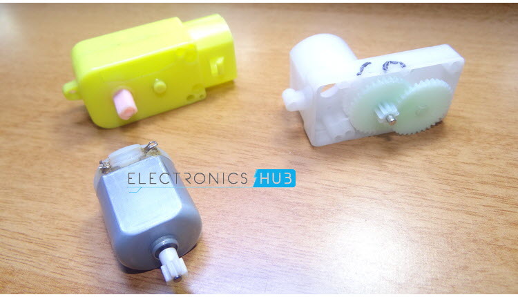
Geared DC Motor
It is a normal DC motor with set of gears attached to the rotor. In normal operation, the gear assembly will increase the torque of the motor but reduces the speed of rotation.
Hence, when the geared motor is powered on, the final rotations of the wheel attached to it will be very less. In generator operation of the DC motor, it will be difficult to rotate the normal motor at maximum speed.
But, when a geared motor is rotated, one rotation of the final gear or wheel attached to it will be equivalent to multiple rotations of the motor at maximum speed.
The DC motor is fitted with a plastic gear system for easy cranking. This geared motor is connected to a wheel with small crankshaft. Consider the two terminals of the motor as positive and negative supply rails.
The positive terminal of the motor is connected to the anode of the diode. The cathode of the diode is connected to the positive terminal of the 1F super capacitor.
The placement of the diode ensures that the charge from the capacitor doesn’t flow back to the motor. The negative terminal of the capacitor is connected to the negative terminal of the motor.
Rotation of the wheel will determine the terminals of the motor. Make sure to check for the direction of rotation of the wheel and determine the terminals of the motor.
The positive terminal of the capacitor is connected to a high power LED via a current limiting resistor. The cathode of the LED is connected to a switch. The other terminal of the switch is connected to negative terminal of the capacitor.
Working of Hand Cranked Generator
When a DC motor is supplied with power, the shaft rotates. The current carrying coil will experience a force due to permanent magnet and as a result, the rotor shaft rotates.
When the operation is reversed, a DC motor works as a generator. When the shaft of the motor is rotated, current is generated in the coils. As a DC motor consists of commutator, the output current is DC.
In this project, a hand cranked generator is designed that can be used to light up a high power LED. The working of the circuit is very simple and is explained here.
When the wheel of the geared DC motor is cranked, DC current is generated in the motor terminals. As these terminals are connected to a 1F / 5.5V super capacitor, it starts charging.
A diode is placed between capacitor and motor so that the charge from the capacitor doesn’t flow back to the motor. The terminals of the capacitor are connected to a high power white LED via a current limiting resistor. A switch is used to turn on or off the light.
For a continuous high speed cranking of 30 seconds, we can expect the light to glow for about 7 minutes at very good brightness. After this time, the brightness of the LED starts decreasing.
Additional circuit can be used to ensure that the output voltage is a stable one. The output of the capacitor can be given to a 5.1V Zener diode along with a Zener resistor of 47Ω.
NOTE
• It is simple DIY hand crank generator that can be used to power a high brightness LED.
• The use of super capacitor i.e. 1F / 5.5V capacitor ensures that it can store a large amount of charge that can be slowly discharged.

6 Responses
Nice
Very nice project.please let me know about the availablety of super capacitor.
How much ampere this generator can supply.
The amperage of the circuit depends on the DC Motor used. Since it doesn’t draw a lot of current (it has a full load current of about 240mA), the generated current will also be in that range (typically less than the full load current).
Can this generate constant 5v ?
Is this necessary that we use a 1F 5.5V capacitor…
can we go for some low value capacitor. Does that affect the working.