The Electrical Wiring Systems are mostly standardized with several rules, regulations and laws. Electrical Wiring must be installed correctly and safely in accordance with electrical regulations and standards. If the electrical wiring is carried out incorrectly or without confirming to any standard, then it may lead to incidents like short circuits, electric shocks, damage the device / appliance or leads to the malfunctioning of device which further causes for the reduction of device life.
Several factors have to be considered before the actual installation work to be done for residential, commercial or industrial wiring. These factors include type of building construction, type of ceiling, wall and floor construction, wiring methods, installation requirements, etc.
Let us discuss some electrical wiring basics, i.e., the concept of electrical wiring, steps involved, methods followed and common types of electrical wiring in brief.
WARNING: This is not a user guide or tutorial on Electrical Wiring. This is just a theory explaining different Electrical Wiring Systems and different possible ways of installing Electrical Wiring. If you are planning a project which involves AC Mains Electrical Wiring, then definitely seek help and guidance from a professional.
Electrical Safety
Before starting any installation work, the first and foremost thing is the concern of safety of the personnel. Electricity is dangerous and direct or indirect contact of electrical equipment or wires with the power turned ON can result in serious injuries or sometimes even causes death. Follow the below steps to maintain the safety at the workplace.

- Always use safety equipment like goggles, gloves, shoes, etc. and avoid any direct contact with live or energized circuits.
- Have the skills and techniques to distinguish the exposed live parts of the electrical equipment.
- Disconnect the source supply while installing or connecting wires.
- The power supplied to the installation must be controlled on the main switchboard, which should consist of circuit breaker.
- Conductive tools and materials must be kept at a safe distance from live parts of the circuit or equipment.
- Use non-conductive hand tools for which they are rated to perform electrical work. If they are used for voltage (or current) rating other than rated, the insulation strength of the tool will breakdown and causes electric shock.
Know more about the electrical safety in this article: Electrical Safety
Distribution of Electricity
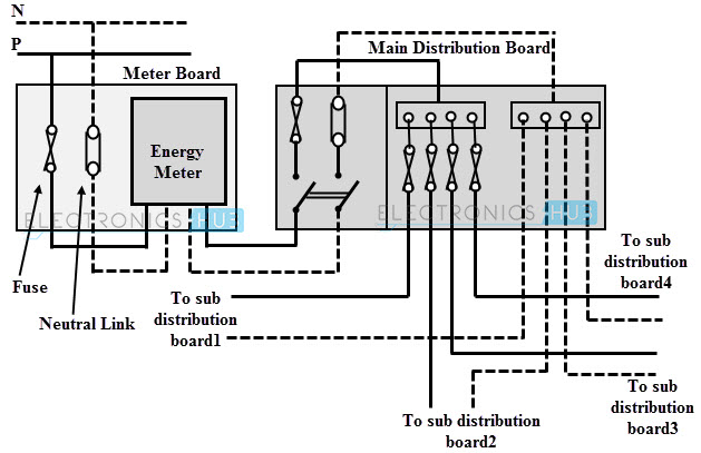
The Electricity Board / Department provides the electric supply up to the outside the consumer’s premises (either residential, commercial or industrial). The consumer has to take the connection from that point to the main distribution board / switchboard at home.
From the main switchboard / distribution board, various types of electrical loads such as fans, lights, room coolers, and refrigerators are connected through respective circuits and electrical wiring.
Image
There are different types of wirings used for connecting the loads to the mains, which can be used for house electrical wiring as well as industrial electrical wiring. Some of these are discussed below.
Types of Electrical Wiring Systems
Electrical Wiring is an important part of a building, be it a residential building (individual houses or apartments), large commercial spaces (office buildings) or industries (factories). There are several methods and systems of Electrical Wiring, which are used for lighting and other power circuits.
The type of Electrical Wiring plays a major role in the overall cost of the installation. So, it is very important to understand what type of Electrical Wiring Systems are suitable for a particular job.
Some common factors to be considered while choosing a particular Electrical Wiring System are:
- Cost of the Wiring System
- Type of Wires / Cables used
- Quality of the Wires
- Type of load (light, HVAC, motors etc.)
- Safety of the Wiring System
- Possibility of future modifications / extensions
- Life of installation
- Construction of the building (wooden, concrete, brick and mortar, etc.)
- Fire safety
Irrespective of the type of Wiring and the choice of Wire, the Electrical Wiring System should be able to protect against regular mechanical wear and tear under normal operating conditions.
Usually, the type of wire determines the Electrical Wiring Systems (or at least their classification). Some of the commonly used Electrical Wiring Systems in Residential, Commercial, Industrial, Auditoriums, etc. are:
- Cleat Wiring
- Casing and Capping Wiring
- Batten Wiring (CTS or TRS)
- Conduit Wiring (Surface or Concealed)
- Lead Sheathed Wiring
Let us now take a look at these Wiring Systems / Installations one by one.
Cleat Wiring
In this, porcelain, wood or plastic cleats are fixed to walls or ceilings at regular intervals, i.e., 0.6 m between each cleat. PVC insulated cables are taken through the holes of each cleat and hence, the cleat supports and holds the wire.
This is an inexpensive method of wiring and is used for temporary installations. Therefore, it is not suitable for home electrical wiring and also it is an outdated method.
Image
Casing and Capping Wiring
In this, cable is run through a wooden casing having grooves. The wood casing is prepared in such a way that it is of a required fixed length with parallel grooves that accommodates the cables. The wooden casing is fixed to the walls or ceiling with screws.
After placing the cables inside the grooves of casing, a wooden cap with grooves is placed on it to cover the cables. This is also a cheap wiring system, but there is a high risk of fire in case of short circuits.
Batten Wiring
In this, insulated wires are run through the straight teak wooden battens. The wooden battens are fixed on the ceilings or walls by plugs and screws. The cables are fitted onto the battens by using tinned brass link clips.
These clips are fixed to the battens with rust-resistant nails. This wiring installation is simple and cheap as compared to other electrical wiring systems also takes less time to install. These are mainly used for indoor installations.
In this type of wiring, Cabtyre Sheathed Wire (CTS) or Tough Rubber Sheathed Wire (TRS) is generally used as the electrical conductor.
Conduit Wiring
In this wiring, PVC cables are taken through either PVC conduit pipes or through steel conduit pipes. This conduit wiring can be either surface conduit wiring or concealed conduit wiring.
If the conduit pipes are run on surface of the walls and ceilings, it is called a surface conduit wiring. If the conduits are run inside the surface of the walls and ceilings and are covered with plastering, it is called as concealed conduit wiring.
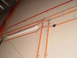
Surface conduit wiring is used in industries to connect the heavy motors. On the other hand, concealed wiring is the most popular and common method of wiring the residential buildings. The conduit wiring is the safest method of wiring and also looks beautiful (concealed conduit wiring).
Lead Sheathed Wiring
This wiring method is also similar the CTS / TRS Wiring except for the type of wire / cable. In this, the electrical conductor is first insulated with Vulcanized Indian Rubber and then it is covered with a sheath of Lead-Aluminum alloy (95% Lead and 5% Aluminum).
Similar to the Batten Wiring, this wiring is also run on wooden batten and are fixed with tinned clips.
Types of Drawings
Electrical Drawings plays an important role in electrical installation works as they convey information about connection of various devices and equipment with mains. The information on drawings provides the complete design or plan of electrical installation and also helps to assemble the various equipment.
Some of the electrical wiring diagrams are discussed below. Before knowing about these diagrams, first you must be aware of and have an idea about various symbols used while preparing drawing and also for understanding the wiring connections. Check out various electrical wiring symbols.
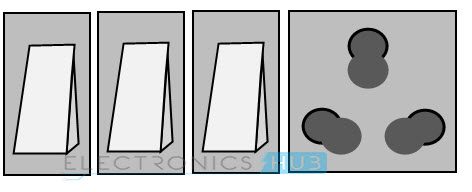
Block Diagram
It is a functional drawing which shows and describes the main operating principles of the equipment or devices. It consists of principle functions or parts represented by blocks and are connected through lines that show the relationship between the blocks.
This diagram is usually drawn before implementing a circuit diagram. It will not give any detailed information about the system and also leaves the information about smaller components. And hence, most technicians have limited interest about this diagram.
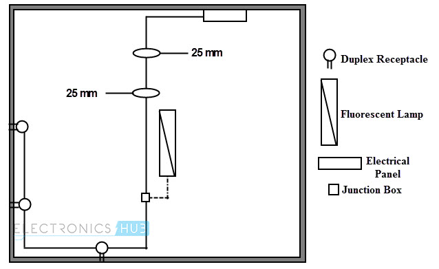
Circuit Drawing (Diagram)
In this, electrical circuit is graphically represented in a simplified manner. It includes the position information (in mm, cm or m) of various elements like light fixtures, receptacle boxes, junction boxes, ceiling fans, etc.
Line Diagram
It is a simplified notation of an electrical system, also called as One-Line Diagram or Single Line Diagram. It is similar to the block diagram except that various electrical elements such as transformers, switches, lights, fans, circuit breakers, and motors are represented by standard schematic symbols.
It consists of symbols to represent the components and lines to represent the wires or conductors which connects the components together.
The line diagram is actually derived from the block diagram. It doesn’t give any layout of the parts and their detail wiring information of the components.
However, you can do wiring by following the information given in this diagram. These diagrams are usually intended to illustrate the working of an electric circuit.
Wiring Diagram
The electrical wiring diagram is a pictorial representation of the circuit, which shows the wiring between the parts or elements or equipment.
It gives detailed information about wiring such that one can get an easy idea of making connection between the devices. It includes relative position, arrangement of the devices and also terminals on the devices.
It shows power supplies and earth connections, control and signal functions (with simplified shapes), termination of unused contacts and leads, interconnection via plugs, blocks, sockets, terminal posts, lead-through, etc.
Wiring Schedule
It is a list of cables or wires used in the installation with its reference number, length, type and the amount of insulation stripping required for soldering the cable. It gives the raceways of the wire and also starting and termination points.
In some complex equipment, wiring table gives the interconnection of the equipment (such as motors and heaters) with starting and finishing reference points. It also includes the wire identification markings, wire colors, size and so on.

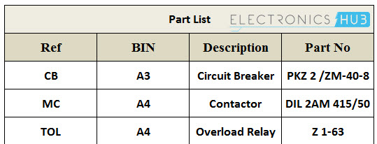
Parts List
Although it is not a drawing, parts list is an integral part of drawing, which defines the various symbols and parts used in other drawings such as wiring diagram, line diagram and block diagram.
It gives the information on the type of circuit component with their reference numbers. This list is useful for identifying, locating and cross referencing the actual component labeled or given in other electrical drawings in order to ensure the choice of appropriate parts before doing the electrical wiring.
Wiring Preparation
As we are discussing the sequence of steps in wiring like understanding the safety, knowing types of wiring systems, understanding the difference among various electrical drawings and symbols, the next step of electrical wiring process is the preparation of wires or cables and electrical tools.
The wiring preparation includes the following considerations.
- The type of conductor can be single solid wire or stranded wire conductor (which is made up of a number of thin stands). Single solid wires are not flexible and are used where rigid connections are required such as power switching contractors. Mostly stranded conductors are preferred for electrical installations.
- The specifications of the wire depend on the several factors like number of strands in the conductor, insulation type, cross section area of the wire, diameter of the strands, etc.
- Choose the wires depends on the color code mentioned by various standards such as brown for phase wire, blue for neutral, green for earth and so on. Click here to know briefly about the electrical wiring colors of the wires or cables.
- Various basic electrical tools are required to do the installation work and some of these tools include cutter, strippers, testers, pliers, etc. These tools are explained in our earlier articles, so please check those electrical tools by clicking here.
- Choose the components such as electrical boxes, switches, receptacles, etc. based on their size and rating.
Start wiring the components together by following the wiring diagrams. Once components, tools and cables are selected, by considering and following the safety of personnel as well as equipment, proceed with installation.
Types of Electrical Wiring
We know that electrical circuit is a closed path through which electricity flows from phase or hot wire to the device or apparatus and then back the source though neutral wire.
Along the way, the electricity path may consist of fixtures, switches, receptacles, junction boxes, etc. So, the wiring may be routed through these elements before actually making connections with apparatus or device.
Majorly, the wiring is divided into two types depending on the way the devices are powered or connected to the supply. They are:
- Parallel Wiring
- Series Wiring
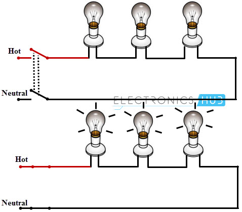
In Parallel Wiring, several devices on the installation are powered on a single circuit. It is the most accepted wiring in homes and industries, in which devices are connected in parallel with the supply source as shown in figure.
In this, both phase (or hot) and neutral cables are routed through the electrical boxes (junction boxes) from which individual receptacles, fixtures, and devices are branched.
The Series Wiring is the rarely used wiring in which hot wire is routed through the several devices and then last device terminal is connected to the neutral wire. It is like an old Christmas lights or serial lights wiring in which one light burnout leads to the shutdown of the entire network.
Examples of Electrical Wiring
For a better understanding of the wiring concept, here we are giving some examples of the wiring circuits, which are commonly used in our homes / offices.
Single Bulb (or any other load) Controlled by a One Way Switch
In this, hot wire is connected to the one terminal of the switch and other terminal of the switch is connected to the bulb positive terminal, then bulb negative terminal is connected to the neutral wire as shown in figure.
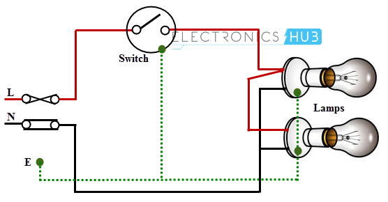
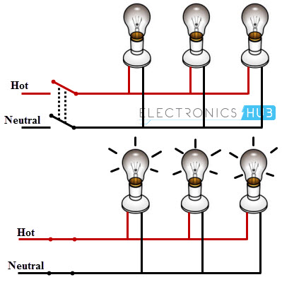
Two Blubs Controlled by a One Way Switch
In this, two bulbs are connected in parallel with the supply wires (phase and neutrals), which are routed by single one-way switch as shown in figure.

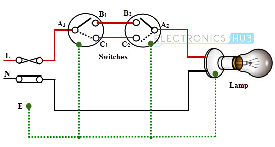
Single Blub Controlled by Two Way Switches
This wiring is also called as Staircase Wiring. In this, a light bulb / lamp is controlled from two different places / sources by using two two-way switches. This type of wiring is used in bed rooms to switch ON/OFF the lamp from two sources (at the bed side and at switchboard). The connection of switches with the lamp is shown below.
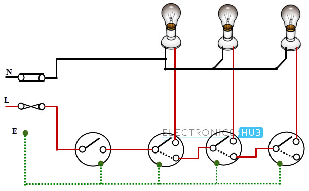
Warehouse Wiring
This type wiring is used in big godowns, long passages, warehouses and tunnel like structures having many rooms or portions. It follows the linear sequence for switching the lights from one end to the other.
When a person leaves one room and enters the next, turning the light switch makes previous room’s lamp to be switched OFF, while the present room lamps to be switched ON. It turns OFF one lamp while switching ON the another. The schematic wiring diagram for warehouse wiring is shown in below.
Fluorescent Lamp Controlled by a One-Way Switch
The switching of fluorescent lamp with single one-way switch through ballast and capacitor is shown in below figure. In this, phase wire is connected to the one end of the switch and another end of the switch is connected to the choke (or ballast). One electrode of the lamp is connected to the choke and other to neutral terminal as shown in figure.

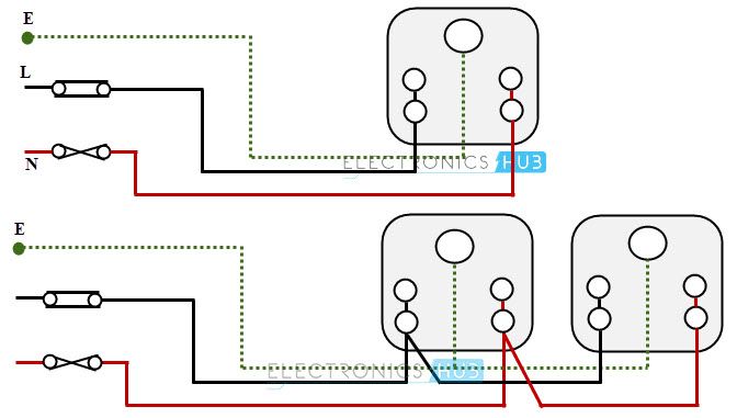
Socket Outlet Wiring
The outlet holds a plug and passes the current through it when the power is routed to the socket through a switch. The single socket connection and radial socket connection are shown in below figure.
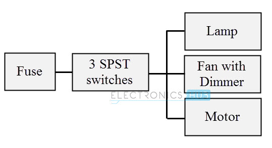
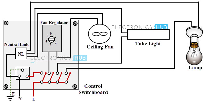
Control Switch Board Wiring
The schematic diagram for a control switch board is shown in the below figure. In this, a ceiling fan, a fluorescent lamp and a light bulb are controlled by appropriate switches.
Conclusion
This is a simple learning guide on Electrical Wiring Systems, Different Types of Electrical Wiring, factors to consider while selecting an installation method, different types of electrical drawing used and also few example wiring diagrams / circuits.

18 Responses
Thank you very much. It is very helpful and very easy to understand.
a nice way of house wiring
Thanks i have learn more as a student of electrical engeniering
thanks
Thanks so much I av learne more as a electrical engineering student
I love your work, it is inspiring
This is so remarkable and adding to knowledge. Thanks so much
Interesting and very easy to understand
Well explanatory
Thanks for your effort
Am grateful thanks very much
Interested and easy to understand
Am grateful and thanks so much
Great ✌️, keep up the good work.
Thanks alot so helpful
Thank you very helpful .
thanks so much, I have added Sam knowledge in my understanding as electrical engineering student
Thankyou very much and I`m so grateful and easy to understand.
Thanks for helping