Grounding is the most important aspect of electrical or electronic system design. Improper grounding results damage to the property and great risk for inhabitants of homes or building. Along with safety to the personnel and equipment, there are many other reasons of electrical grounding including serving as a reference point and to establish a return conductor, etc.
When working with electrical installations, electrical grounding is one of the best safety devices that protect the personnel and equipment from high dangerous currents.

What is Electrical Grounding?
A ground is the conductive connection between the earth or other conductive material in the place of earth and an electric circuit or a piece of equipment.
The principle reason of facilitating the grounding is to enable immediate diversion of heavy fault current in the event of a circuit fault, there by protection is provided against electric shock hazards to people and animals.
In grounding or earthing, electric circuit or apparatus is connected to the earth by a metallic conductor of negligible resistance. This conductor should have good conductivity, high tensile and rupturing capacity and must be of corrosion or erosive resistant.
The earthing is classified into two major types, namely, system or neutral grounding and equipment grounding.
The system grounding is the connection from one of the current carrying conductors of an electrical power system or of an interior wiring system to the earth or ground.
Mostly, neutral conductor is connected to the earth in system ground and today almost all power systems operate with grounded neutrals.
In this, the neutral terminal of various equipment such as generator, motor, transmission and distribution equipment, transformer, etc. is connected to the earth either directly or through a resistance, or a reactance.
The purpose of the system grounding is to provide protection against unbalanced voltages with respect to earth, arcing grounds, various electrical faults, and protection from the lightning.
The equipment grounding is the connection of one or more non-current carrying metal parts of a wiring system or equipment to the ground.
The non-current carrying metal parts include motor body, transformer tank, switchgear metal enclosures, conduits of the wiring, etc. The purpose of this grounding is to protect the personnel getting in touch with equipment during the faults in it.
Why Grounding is Needed?
Safety to Personnel and Equipment
Grounding provides the safety to personnel and equipment by ensuring operation of protective control gear and isolation of the faulty circuit under the following cases.
Insulation Failure
If any conductor insulation is damaged and if it touches the ground , the electric current will flows through the ground path as shown in below.
The flow of fault current is sufficient to operate the protective device, if the impedance of the ground path is low. So the protective device isolates the circuit, thereby avoids the flow of current through non-current carrying parts.
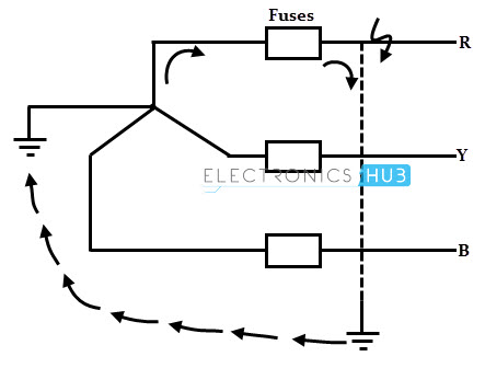
Accidental Contact between Wires of High and Low Voltage
When HT wires get in touch with LV wires (as shown in the figure), a heavy fault current will flow through the secondary of the transformer next to earth connection of the transformer and back to the high voltage system.
This fault current operates the protective devices on high voltage side and hence it trips the circuit. Therefore, grounding provides the means to operate the protective devices under fault conditions.

Over Voltage Protection
During lighting strokes, unintentional contact with higher voltage lines, or line surges in the circuit can cause a serious high voltage in the power distribution system. So the grounding provides the low resistance path in order to send an extra charge safely to the ground.
Voltage Stabilization
Earth serves as a constant potential reference in a power system network against which other potentials are measured. In electric power system, there are many sources for producing the power.
So the ground provides a common reference point for these sources. Without the ground, it would be difficult to calculate the relationship between the various voltage sources to one another and it may lead to serious electrical hazards.
To Save Installation Cost
In some power transmission and telegraph circuits, ground itself used as one of the conductors of the transmission system in order to save the cost of installation for a separate conductor.
Types of Grounding
As we discussed above that grounding is mainly classified into two types as system grounding and equipment grounding. Let us discuss these types in brief.
System or Neutral Grounding
The major consideration in neutral grounding system is to provide safety to the human beings and to maintain safe working of electrical appliances, under the assured operation of protective relay system.
This offers improved service reliability, greater safety, reduction of transient voltages, and improved fault protection. The commonly used methods of system grounding include
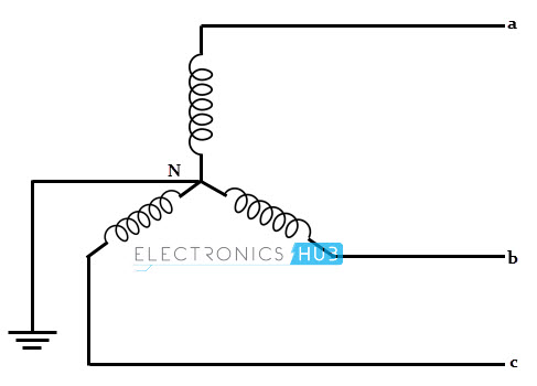
Solid Grounding
In this, the neutral conductor is directly connected to ground without any impedance between the neutral and earth as shown in figure. It is simple and inexpensive method that it requires no extra equipment.
It minimizes the over voltage in the faulty phase during a phase to ground fault which results in reduction of stress on insulation on the faulty conductor. This method is most commonly used in industrial and commercial power system operations.
The disadvantage of the solid grounding is that a severe flashes or arcing hazards are caused during high line to ground faults. These arcs may cause the burning of protective devices.
This system becomes unstable as it has to bear a huge current during phase to earth faults. So this grounding is usually employed where the circuit impedance is sufficiently high in order to keep the earth fault current within safe limits.
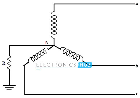
Resistance Grounding
In this, a resistor is used between the star point (neutral point) and earth. Resistance limits the magnitude of an earth fault current in safe limits. This resistance value should neither be very high or very low. If the resistance is very high, the system will become ungrounded neutral system.
On the other hand, if this value is very low, the system will become a solid grounding system. Therefore, the value of the resistance should be in such a way that the fault current is limited to safer value while permitting the operation of earth fault protection system.
The disadvantage of this system is that there is an enormous energy loss in the neutral earth resistance due to the dissipation of the fault energy and also it is costlier than the solid ground system.
This system is employed in plants and mills where the continued operation of the process is the major requirement during fault conditions.
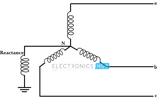
Reactance Grounding
In this, a reactor is used in place of resistor. Similar to the resistance, reactance must be chosen to suit the requirements of protection, or to control the inductive interference. The reactive part of the fault current is compensated by this reactor.
These are used when the amount of current reduction is small. This is because reactor of low resistance to handle large quantities of current can be built at low cost as compared with the resistor for the same current limitation.
The disadvantage of this system is that high transient voltages appear across the system under fault conditions.
Also, for the same fault conditions, the fault current required to operate the protective device in resonant grounding is higher than that of resistance grounding. Due to these disadvantages, this method of grounding is not employed nowadays.
Arc Suspension Coil Grounding or Resonant Grounding
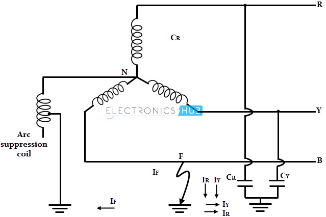
In this, an adjustable reactor is placed in between the star point or neutral point and earth in order to balance the fault current with capacitive current. We know that capacitance exists between each line and earth.
So, the capacitive currents through these capacitors is responsible for producing the arcing grounds (repeated arcing across the fault due to capacitances).
 Arc suspension coil grounding
If an appropriate value of inductor is connected in parallel with the capacitance of the system, the fault current If flowing through the inductor will be in phase opposition to the current Ic flowing through the capacitor.
If the inductance is adjusted such that IL = Ic, the resultant fault current will be zero. This is called as resonant grounding.
Therefore, this method completely prevents any damage to the system by an arcing ground. The above figure shows the resonant grounding in which an arc suspension coil or Peterson coil is connected between the earth and neutral terminal. However, the coil must be readjusted every time as the capacitances changes from time to time.
Equipment Grounding
As discussed earlier that connecting metallic enclosures or non-current carrying metal parts of the electrical equipment to earth is called as equipment grounding.
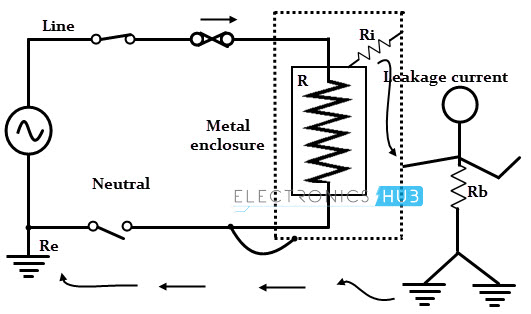
Consider that an electrical equipment of resistance R is connected across the supply mains and assume that it is not grounded or earthed as shown in figure below. Let Rb be the resistance of the body of a person who touches the apparatus while maintaining contact with the earth as shown in figure
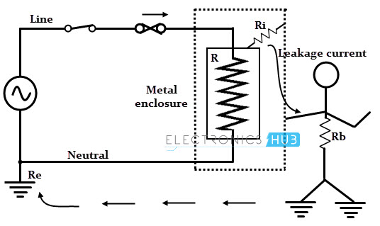 The current from the mains has two paths; one path is through the apparatus and other through insulation resistance of the apparatus next resistance Rb of the body and finally through earth resistance Re to the neutral of the supply.
If the insulation resistance is infinity, no leakage current flows through the body and hence no shock is experienced by the person.
If the insulation of the apparatus is failed or defective, the insulation resistance becomes zero and hence the leakage current from mains passes through the body of the person and its magnitude depends on the body resistance. This current is quite sufficient to give a shock to the person.
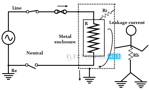
If the equipment enclosure is connected to the ground neutral wire, the leakage current flows through the enclosure and back to the neutral wire in case of insulation failure.
Therefore, the equipment is maintained at earth potential and the person or operator would not experience any shock as the leakage current is diverted to the neutral ground path.
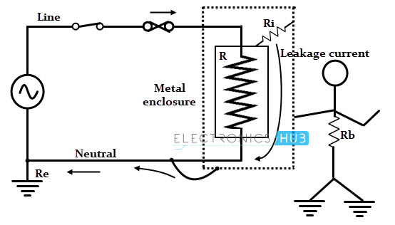
This method is not safe because if by any chance the neutral is opened under the fault condition, the person in contact with the enclosure would receive a severe electric shock as shown in below.
Suppose, the equipment is grounded with separate ground wire such that the path offers zero resistance to the current flow.
When the person touches the equipment in the event of insulation failure, the fault current is diverted through the ground path rather than through the body of the person. Hence the severity of the shock is avoided by this equipment grounding.

One Response
i need all the details about this electronics and circuits theory in a clear manner with complete details