In this project, we will see how to design a simple DIY Universal Remote using Arduino. Using this remote application, you can control various electronic appliances like T.V., A.C., DVD Players, etc.
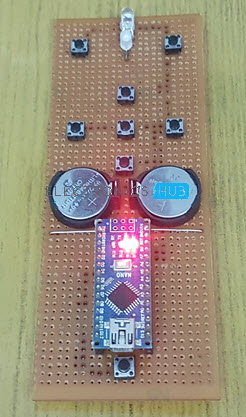
I have implemented the Universal Remote using Arduino Nano and places it on a small perf board along with all the buttons, power supply etc. The final build looks something like this.
Introduction
An IR Remote control is a line of sight based wireless communication device that works in tandem with an IR Receiver. You can find IR Remote controls and corresponding IR Receivers in almost all major electronic appliances like televisions, air conditioners, TV boxes, audio players and many more.
The main problem with this setup is that each device has its own IR Remote control and the more the number of appliances you have, the larger the pile of remote controls.
What if you have a single remote control that can control, if not all then majority of your electrical appliances? This concept is known as Universal Remote Control and it is already existing in the market.
Bringing the same concept to makers and hobbyists, a DIY Universal Remote using Arduino is developed in this project. The reason for building your own Universal Remote using Arduino can be as simple as the satisfaction of building a practical application with your own hands or can be to bypass the cost of an already existing universal remote control from the market.
Principle behind Universal Remote using Arduino
The main principle behind the implementation of an Arduino based Universal Remote Control is very simple. First, using an existing remote control of any appliance like TV for example, the IR Signals are decoded.
These decided signals are then used in the final application to emit the corresponding infrared signals using an IR Emitter LED.
Decoding the IR Signals using Arduino
The first logical step is to decode all the infrared signals from the existing remote controls. I have a Sony TV and a Voltas AC. Using these two remote controls, I have decoded the basic buttons like Power, Volume Up, Volume Down, Previous, Next, Source for the TV and Power, Temperature Up, Temperature Down, Swing, Fan, Turbo for the AC.
Before proceeding with this, I recommend you to go through this simple project called “Arduino IR Receiver Tutorial”, where I have discussed all the important aspects to setup an IR Receiver with Arduino and decode the signals.
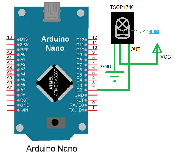
Circuit
For now, the circuit diagram for decoding the TV and AC Remote keys is shown below, where I have used Arduino Nano along with TSOP1740 IR Receiver.
Code
The code for decoding IR Signals is given below.
All the decoded signals will appear on the serial window. Make a note of all the decoded values.
NOTE: A special library called “IRremote” is used in this project. You can directly install it using Arduino IDE’s Library manager and search for IRremote by shirriff.
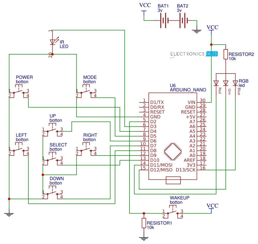
Circuit of Universal Remote using Arduino
Now that we have decoded all the necessary signals from the original remotes, we can now proceed with the actual build of the Universal Remote using Arduino. The circuit diagram is shown below.
Components
- Arduino Nano
- IR LED
- Push Buttons x 8
- CR2032 Battery x 2
- CR2032 Battery Holder x 2
- RGB LED x 1
- 10KΩ Resistor x 2
- Connecting Wires
- Perf board
- Female Header strips (for Arduino Nano)
Circuit Design
First, an IR Led is connected to Digital IO pin 3. Then the buttons are connected as follows:
Button
Arduino Digital IO Pin
Power
4
Mode
5
Up
6
Down
7
Left
8
Right
9
Select
10
Additionally, there is a Wakeup button connected to Digital IO pin 2. Digital IO pin is pulled down using a 10KΩ Resistor, while all the other button pins are pulled up internally. The other ends of all the buttons (except Wakeup button) are connected GND. The other end of the Wakeup button is connected to VCC.

An RGB LED is used to indicate the appliance selected. The RGB LED used here has a common anode terminal, which is connected to VCC through a 10KΩ Resistor. The R, G and B ends of the LED are connected to pins 11, 12 and 13 respectively.
The entire system is powered by a couple of CR2032 3V Lithium cells in series.
Code
Following is the code for the application Universal Remote using Arduino. From the previously collected values, place the corresponding values in the appropriate arrays provided for TC and AC in the code.
These arrays are named tv_onoff[], tv_volup[], tv_voldown[], tv_prev[], tv_next[], tv_source[] for TV related data and ac_onoff[], ac_tempup[], ac_tempdown[], ac_swing[], ac_fan[], ac_turbo[] for AC.
NOTE: An additional library called “LowPower” is used to put the Arduino to sleep after a preset time to save battery. Download this library from this GitHub page.
Working
After inserting the decoded values and uploading the code to Arduino Nano, you can start using the application as a Universal Remote control. First, press the mode button to select the appliance. I have assigned Red LED for TV and Green LED for AC.
So, by pressing the mode button you can select between TV and AC and the Led acts as a visual indicator. Once the mode is set, you can use the remote for that particular device. If no key is pressed for a period of 10 seconds, the LowPower library will kick in and puts the Arduino to sleep.
Use the Wakeup button to wake the Arduino.
Conclusion
A simple but very useful DIY Project called Universal Remote using Arduino Nano is designed here. Using this application, you can control a number of electronic appliances with the help of a single remote control.
