Communication over Radio Frequency has many advantages as it doesn’t require a line of sight connection between the transmitter and receiver as in case of Infrared communication.
The range of RF communication is very high when compared to IR communication. In this project, a wireless transmitter and receiver system using RF modules (RF Transmitter and RF Receiver) is implemented.
An RF Transmitter and Receiver pair is used for wireless communication. The wireless data transmission is done using 433 MHz Radio Frequency signals that are modulated using Amplitude Shift Keying (ASK) Modulation technique.
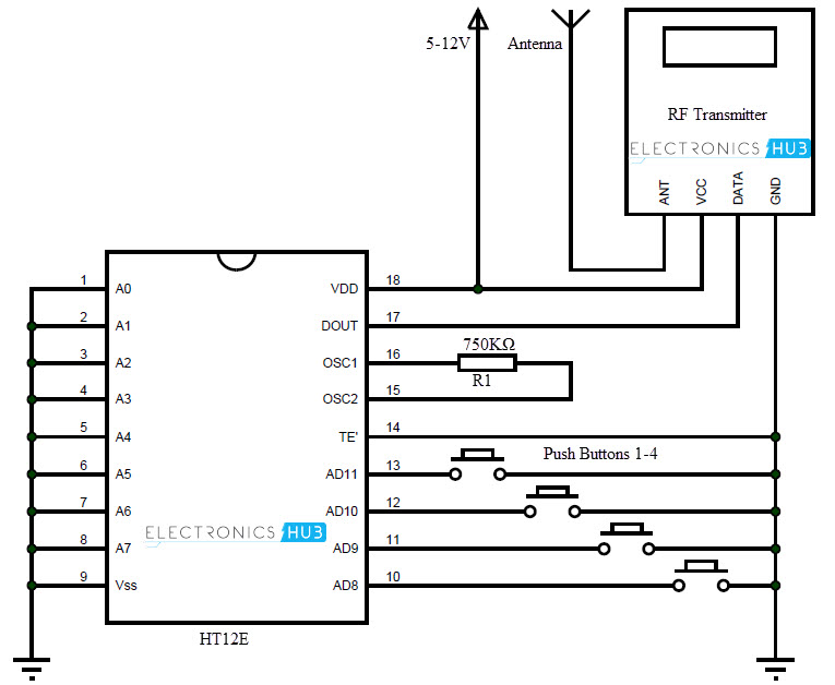
In order to implement the wireless transmitter and receiver, we use an encoder IC HT12E and a decoder IC HT12D.
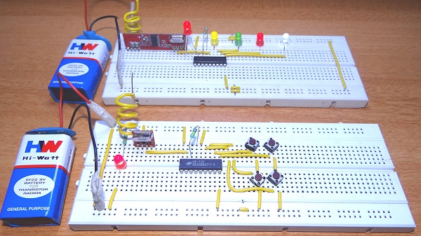
Wireless Transmitter and Receiver using RF Modules
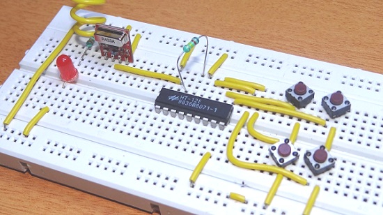
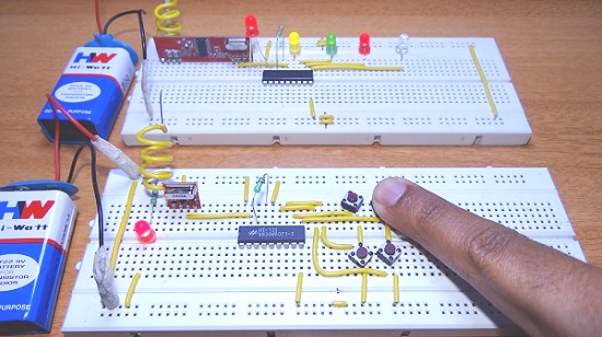
The circuit is divided into transmitter and receiver sections. The transmitter section consists of an RF Transmitter, HT12E encoder IC and four push buttons.
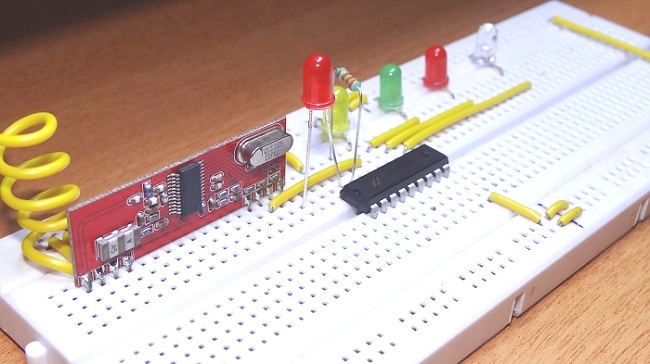
The receiver section consists of RF Receiver, HT12D Decoder IC and four LEDs. An extra LED is connected to VT (Valid Transmission) pin of the decoder IC. This is used to indicate a successful transmission of data.
A 750 KΩ resistor is connected between the oscillator terminals of encoder IC. This is to enable the oscillator.
Similarly, a 33 KΩ resistor is connected between the oscillator pins of decoder IC.
Output
Transmitter
Receiver

Component Description
RF Transmitter and Receiver Modules: The wireless communication between transmitter and receiver sections is achieved using RF modules. A 433 MHz transmitter and receiver pair are used in this project.
HT12E
It is an encoder IC that converts the 4-bit parallel data from the 4 data pins into serial data in order to transmit over RF link using transmitter.
HT12D
It is a decoder IC that converts the serial data received by the RF Receiver into 4-bit parallel data and drives the LEDs accordingly.
Working
The aim of this project is to implement a wireless transmitter and receiver using RF modules. It uses radio signals to transmit the data. The working of the project is as follows.
The transmitter and receiver sections are placed at a distance of at least 20 meters. In order to show the working of wireless communication between transmitter and receiver, 4 LEDs at receiver side are controlled by 4 buttons at transmitter section.
The HT12E encoder IC converts the 4-bit data from the 4 data pins that are connected to buttons into serial data. This serial data is sent to RF transmitter. The RF transmitter transmits this serial data using radio signals.
At the receiver side, the RF receiver receives the serial data. This serial data is sent to HT12D decoder IC which converts into 4 bit parallel data.
The 4 data pins of decoder are connected to LEDs. According to the buttons pushed, the LEDs can be turned ON or OFF.
Applications
- As RF Modules doesn’t require line of sight communication, the transmitter and receiver can be isolated over a distance and data can be transmitted successfully.
- The wireless transmitter and receiver can be used in car door and garage door controllers.
- They can also be used in home automation systems.

62 Responses
I made the connections correctly,but the circuit is not working.The i.c is getting heated very badly.
REMOT OSC1,OSC2 CONNECT 1MOHM RESISTOR
AND RECIEVER OSC1,OSC2 CONNECT 47KOH RESISTOR
Wow great detail.
I just have a question.
I have a Wireless RF transmitter and receiver 433 MHZ – RXB6 Module and a RasberryPi2.
I want to create a Wireless Button for WebCam to take pics, the webcam is connected to a RasberryPi 2.
My question is:
Do I need to have the HT12D chip?
Hey , where is the antenna in this video and you are turning on-off the LED using switch…??????
How is it possible?????
Antenna is not needed. Without the antenna also the RF Transmitter can transmit upto 50-60m max.
How can I indicate anteena in this circuit?!
anyplace you wish… indicating it doesn’t mean ‘schematic’ diagram location… which is TX output. Location may be on the roof as you decide.
I made the connections as mentioned by you in article. But on pressing the switches the LEDs are not turning off. As soon as I apply voltage to both the circuits, LEDs get lighten up but on pressing toggle switches they are not being turned off.
Kindly help.
Hi, Please check the connections once again. Try to turn ON the receiver circuit before the transmitter circuit.
i just made the connections .now my question is that you had applied the LED in the transmitter ckt with resistor.
do i know the resistor value?
How can i increase its range ??
Range can be extended by increasing the length of antenna. For maximum range, you want to use an antenna of the proper length of 1/4 * lambda. At 433 MHz, this comes to 17 centimeters. It is best to stretch out the antenna to its maximum length but it will also work when coiled up a bit.
Plz send me detail information for how to increase antenna range
Or any video.
Thank you
Do I need to have the HT12D chip?
HT12E and HT12D are the encoder and decoder ICs. You have to use them to successfully transmit the data. An alternative way is to use two microcontrollers at both the ends and program them according to the function they have to perform (encoding and decoding the data).
Yes! If you want the circuit to work right.
How would I make this project with a 2KM Long Range RF link kits w/ encoder and decoder connected to them. I am new with breadboards and I have a project that i need to make these connections work.
Hi, 2Km with these modules might be possible by increasing the transmitter power and designing a half wave dipole antenna.
where to buy all of this component in mumbai ????
Medical store, specially of Apollo hospitals.
How to make LED to switch on when button is clicked ?
Hi, You can use a simple PNP transistor like BC558 for example to turn on the LED upon pushing the button.
Hi, I followed your schematic, but the problem I have encountered is that when I push the buttons nothing happens. Please Help
Hi, Please check the connections once again. Try to turn ON the receiver circuit before the transmitter circuit.
Can you explain why you picked the specific values 33k and 750k ? I used a 680 k instead of 750 k and it works fine. Do you know why? Great tutorial btw.
Hi, If you refer the data sheets of HT-12E and HT-12D, you can understand how to select the Resistors for oscillators (ROSC). In the data sheet, for a 5V supply, if the ROSC of HT-12E is 1.1M, then ROSC for HT-12D should be 51K. The combination of 750K and 33K might not be correct, but with breadboard circuits, even with exact values, you might not get the result.
how to use multiple decoders on the single rf pair..can we use address lines in the encoder for that??
Can the transmitter work on 3V battery cell? If it is, I can miniaturize the transmitter.
hey anusha,
i want to control three motors,how do i do it?
please tell me,,,,,,,,,this rf system’s maximum range………and how to increase the rang
Hi… if I were connect two motors instead of 4 LED’s, how should I give the connections? and should I change the resistor for using motors?
Great stuff
Is it compulsory to use 750k resistor and 33 k resistor? Can i use any other combination of resistors?
If yes , then please say those combinations
The resistors are for the Oscillators in the Encoder and Decoder ICs. Depending on the supply voltage, those values change. For example, at 5V supply, the resistora are 1M Ohms and 51K Ohm for Encoder Oscillator and Decoder Oscillator respectively. Please refer to the data sheets of both Encoder and Decoder ICs.
Hi, I made this work but suddenly my receiver has stopped working. I then took out the antenna …17.25cm wire and it works without it. What happened!? I still have the antenna on the transmitter but once I place the antenna on the receiver side it doesn’t work. Where am I going wrong?
my valid transmission led is constantly blinking .why?
Can we use motion sensors instead of push buttons and also buzzer for leds.If not ,why?
Also when we use them which I said ,is there any use of extra voltage or have to change in resistance??
Please reply,I badly need ur answer
Thanq
No led is lighting why?should I short circuit all the 1-10 pins of ht12 to ground
do rf transmitter and receiver need programming to run rf based projetcs.?
I have made same connection but on same breadboard but it is not working properly in place of 4 LED’s only 1 LED is glowing and even that LED is not showing any effect on turning on/ off switch can you tell me what mistake I’m doing
Shall I use speaker at receiver in place of LED???
thank you very much…it worked for me…..
dude were did you get the 433 transiever, i have looked for it all over the electronic stores in my city.
on the receiver side theto led at vt doesnt glow .i.e, the transmission doesnt take place andin my circuit isto absoulately correct
Can it works a fixed address transmiter and reaciver
How i make the connection to make fixed address.
where is the audio source?
What audio source?
may be i want to transmit my conversation inside my room to a distance of 1 km ,where can i plug microphone and pre amplifier stage?
What website can I go to so I can buy every part needed for this build?
how do i use it to turn led on when the receiver is the transmitter
thank u
how can i isolate the distance of RF upto 2 meters only is there any technique??
it doesnt work
I want to transmit data at the range of 100 meter . is it possible to transmit data at this range?
Please reply as early as possible
What are the new applications that are performed from RF transmitter and receiver in 2018?
I need two of these at the same time for the application. I wondered if there was addressing so that the signals do not go over top each other.
thanks
Thanks for your efforts..
can i use this design for ground penetration application? if i send signal from RF transmitter to ground , it should a reflect signal will be produced depending on ground layers and receiver will catch it ? is it possible?
thanks alot
What is the max distance range between two modules?
could I take the buttons out and still have the LED light up on the transmitter circuit
Thanks for the report !!!!
Is there a way to pair transmitters and receivers so that multiple sets can operate in the same area without interfering with each other?
How can i control a servo motor using these project