In this project, we have built an Ultrasonic Rangefinder using 8051 Microcontroller and Ultrasonic Sensor. We have different ways to measure the distance. One way is to use Ultra Sonic Sensor or Module for distance measurement. This article explains you how to measure the distance using 8051 microcontroller. This Ultrasonic Range Finder system measures the distance up to 4 meters with an accuracy of 3 mm.
Output Video
Ultrasonic Rangefinder using 8051
Principle of Ultrasonic Rangefinder
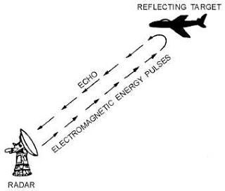
Generally, the distance can be measured using pulse echo and phase measurement method. Here, the distance can be measured using pulse echo method. The ultrasonic module transmits a signal to the object, then receives echo signal from the object and produces output signal whose time period is proportional to the distance of the object. The mechanism of the ultra sonic sensor is similar to the RADAR (Radio Detection and Ranging).
This circuit calculates the distance of the object based on the speed of the sound wave at normal temperature and displays the distance on LCD.
Also Get an Idea about How to Interface 16×2 LCD with 8051 Microcontroller
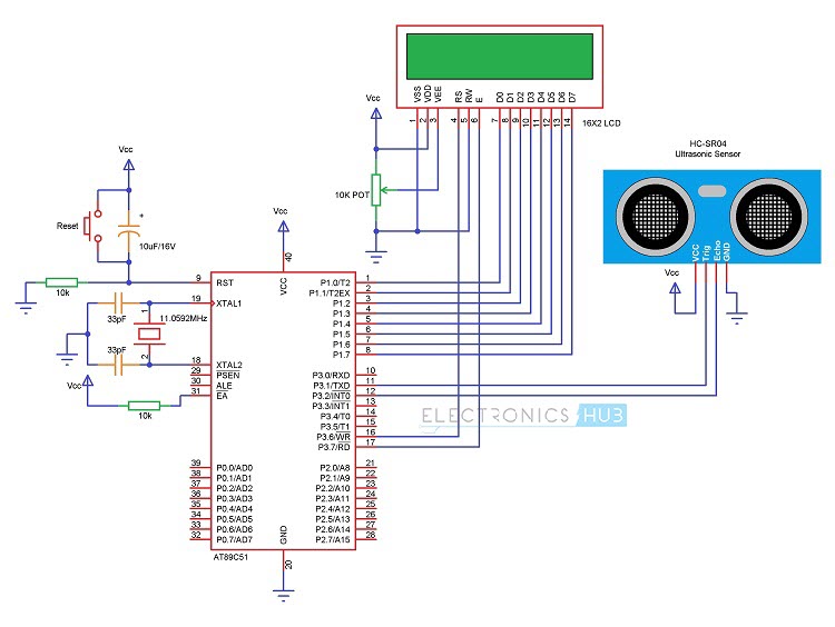
Circuit Diagram of Ultrasonic Rangefinder using 8051
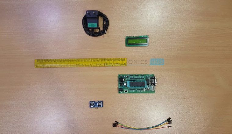
Components Required for Ultrasonic Rangefinder
- AT89C51 Microcontroller
- 8051 Programming board
- Programming cable
- HC – SR04 Ultrasonic Module
- 16 x 2 LCD
- 10KΩ Potentiometer
- 10µF / 16V Electrolytic Capacitor
- 2 x 10KΩ Resistor (1/4 Watt)
- 0592 MHz Crystal
- 2 x 33pF Capacitors
- Push Button
- Connecting wires
- Power Supply
- Keil µVision Software
- Proteus
- Willar Software
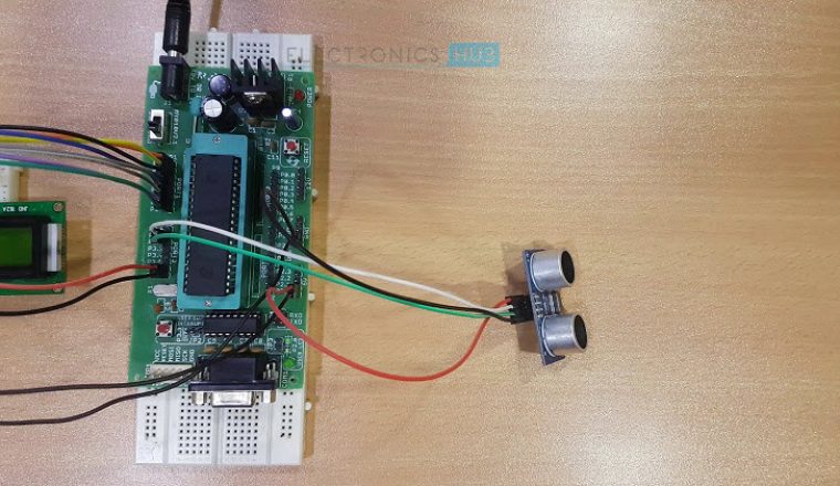
Circuit Design of Ultrasonic Rangefinder
The major components in this project are AT89C51 Microcontroller, Ultrasonic Sensor and LCD Display. The TRIGGER and ECHO pins of the Ultrasonic Sensor are connected to the P3.1 and P3.2 pins respectively. LCD data pins are connected to the PORT1 of the microcontroller and controller pins RS, RW and EN are connected to the P3.6, GND and P3.7 respectively. Here, the LCD (Liquid Crystal Display) is used to display distance of the object. 10KΩ POT is used to vary the contrast of the LCD. Power supply pins of the microcontroller, LCD and Ultrasonic Sensor are connected to the 5V DC.
Ultrasonic Module (Ultrasonic Sensor)
HC – SR04 Ultrasonic Module works on the principle of SONAR and is designed to measure the range of the object in small embedded projects. It offers excellent range detection with high accuracy and stable readings. The operation of the module is not affected by the sunlight or black material.
Features
- Resolution of this module is 3mm
- Ranging distance is 2cm to 400cm (4 meters)
- Angle measurement is 30 degrees
- Trigger input pulse width is 10µs
- Required current 15mA
- Frequency 40 KHz
Pin Configuration
- Vcc: This pin is connected to the positive 5V DC.
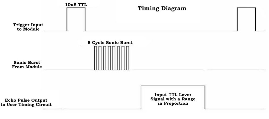
- Trigg: The trigger signal is applied to this pin for starting the transmission. This signal must be HIGH for 10µs. When a valid trigger signal is applied, it generates 8 pulses of 40 KHz.
- Echo: At this pin, module generates the signal whose time period is proportional to distance.
- GND: This pin is connected to the ground.
Related Post: Non Contact Digital Tachometer Circuit Design using 8051 Microcontroller
How Ultrasonic Rangefinder using 8051 Circuit works?
When HIGH pulse of 10µs is applied to the TRIG pin, the ultrasonic module transmits 8 consecutive pulses of 40 KHz. after transmitting 8th pulse the ECHO pin of the sensor becomes HIGH. When the module receives reflected signal from the object, the ECHO pin becomes LOW. The time taken by the signal to leave and return to the sensor is used to find out the range of the object.
Distance in centimeters = (Time/58)
Object distance in inches = (Time/148)
Distance can also be calculated using speed of the ultrasonic wave 340m/s
Download Project Code
Algorithm for Program
- Send HIGH pulse for 10 micro seconds on TRIG pin
Initially P3.1 = 0;
P3.1 = 1;
delay_ms (10);
P3.1 = 0;
- Wait until the module transmits 40 KHz pulses. When 8thpulse is transmitted echo pin becomes HIGH, TIMER0 starts counting, when input INT0 goes LOW and timer counts the time
while (INT0 == 0);
while (INT0 == 1);
- TIMER0 value is equal to the time taken by the signal to go forward and comeback so we need to take only half time.
Time required = TIMER0 VALUE/2
- The speed of the ultrasonic pulse is nothing but the speed of sound which is 340.29 m/s or 34029 cm/s
- Distance = speed * time = 34029 * (TIMER0) / 2
- At 11.0592 MHz, TIMER0 gets incremented for 1µs.
Range = 17015 * TIMER0 X 10-6
- Target range = TIMER0/58 cm.
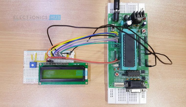
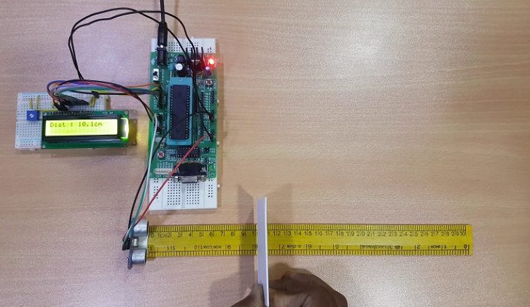
How to Operate?
- Initially burn the program to the microcontroller
- Now give the connections as per the circuit diagram
- While giving the connections make sure that Vcc of ultrasonic module is connected to 5V DC
- Switch on the board supply
- Place the obstacle in front the ultrasonic module, now you can observe the distance on LCD.
- Switch off the board supply.
Ultrasonic Rangefinder Project Applications
- Used to measure the obstacle distance.
- This system used in automotive parking sensors and obstacle warning systems.
- Used in terrain monitoring robots.
Limitations of the Circuit
- This system is not able to measure longer distances.

58 Responses
NICE CONCEPT
how can we overcome the limitation of ultrasonic range finder?
HC SR04 and AT89s51 are not available on proteus…plz tell me how to get these parts???????
download libraries for both , and place it in library folder!!
you have to get files from
google to your proteus’s LIBRARY folder
i cant find the sensor module in the proteus library please help
U can connect any 2 switch because this sensor is 2 bit sensor so u can use switch for protious
i want to build one help me.
i need this project code to create different project but still using the same concept as yours. my project is about to detect hazard in long distance for a smart car. can you send me the code by email?
Need a project code im trying to make a similar one for my hobby so please share project code to my id is also fine..
thank you
Nikhil Shetty
I am an electronic engineer and electronic hobbyist .I want to make same project . send me source code..
1. Why you need this project code?
Because i wanna take your coding as a reference to our viva in our university.
2.Are you trying to make the same project or different one?
No. Because our project required us to use two microcontroller boards with some other different components. And besides, my microcontroller board are different type from yours.
3.Give us more details about your project.
My project required us to make a smart system in a vehicle with using two or more microcontroller boards. We are required to use an embedded c programming for our project.
I hope you can consider our reasons and help us for our project. ^_^
Code is uploaded Long back..Please check the article
I am a Computer Engineering student, and I am taking a course this semester called Embedded Systems, so I would need this code to practice more and to try to understand this better, because so far, we’ve only been taught about LED Blink, and I want to go ahead of others in learning and understanding this course, and I also want to make a project like this, but in PIC18F microcontrollers. please send me the code. For educational purposes. Thanks
i want the software for this project can u please send it to me
I want to do this project using PIC..So please can you help me with the project code?
Thanks In Advance..!
I need to make a ultrasonic distance finder project for my third year engineering mini project. kindly help.
please email the code.
will really appreciate the help.
1.for reference i need this project code.
2. i am designing similar kind of project bt in different application.
3. i am using this concept in vehicles to prevent accidents.
1. I need the code for the college project.
2. We are trying the exact same project.
hi..
i want to do this as my mini project in engineering..
plz send the code…
Sir , Thank u for giving such amazing knowlege about this project. I am interested to make this project .I am making the same project for exploring my skill.and I also required code for this one.
Thank you once again.
Plz sir ,Hurry send code on my mail.
I need the code for this project ‘Ultrasonic Range FInder’. I am a 4th year Electronics & Communication engineering student and making this project for my ‘Final Year Major Project’. My email is – abhi.sgh11593@gmail.com Thanks 🙂
Code is already uploaded in the article.Please go through the article completely
Very good, please requests you to send m code
Download code from the same post
hi just i want to make an obstacle follower robo using two ultrasonic sensor with 89s52 and 16×2 lcd……
can i use both interrupt pin at atime for both ultrasonic sensor (one for left and other for right ….)pls,,,suggest me ………….
…….using ur code already i run which work fine ……..
………
Yess you can use both interrupts…
Very nice I want the code please
After completing all the connections and turning on the power supply the lcd display only shows “Range finder” and it does not show the distance ………..what could be the problem..??
Please help..
Check the sensor….
I am trying ultrasonic sensor based distance meter. Also i will display the distance in LCD. This is what i am intended to do for my academic project.
I am btech student..I want the code as m working on same project..
Code is present in the article itself.you can simply download it..
Kindly send us the programming code. not able to get the code
how many counts are required in timer0 to show a range of 1cm?
softwares needed for this projects plz tell me!!!
HC SR04 library for AT89s51 are not available on proteus…plz tell me from where can i download these parts
hello, what software for this project? urgent. ty
will u please help me for the code of my other project just related to ultrasonic sensor and microcontroller actually i want recoznize shape and size of object detected by ultrasonic sensor.
please help me to write a code of my project different from this but related to it , i want to recognize the shape and size of the object detected by the utlrasonic sensor.
I am interesting to construct this project..please show how to construct it
What I can do for distance to be more than 4m ?
hc-sr04 sensor is not available in proteus then wht should i do….???????????????????????????
Hi, Yes. We do not have a Proteus library for Ultrasonic Sensor. Try to build the circuit with a physical module.
I want to make a speed checker and overspeed detector but there are some problems like how to sense 2 vehicles running side by side and differentiate between them and another problem is how to read the speed of all the vehicles passing through the fixed points
Hi, You should probably go with a laser type speed gun design. Ultrasonic Sensor wouldn’t be useful in your case.
Hello everyone.The Ultrasonic Sensor has a Test Pin .What should I do with that?Please i need a reply ASAP
Hi, There are usually 4 pins on HC-SR04 Ultrasonic Sensor (VCC, GND, Trigger and Echo). There is nothing as Test Pin. Can you provide a link to the particular module you are using?
hi guys
Is there anyone to send me a code for(r Range finder by using at89c51
) in assembly language
Hi,
I’m interfacing HC-SR04 sensor with lpc2148 microcontroller & checked the above 8051 code
for reference, but the o/p I’m getting as 0 cm on lcd…
The operating voltage of lpc2148 controller is 3.3v, I have connected to same voltage only,
instead of 5v, will it work?
can this hex file be used with other 8051 based controller like p89v51rd2 from nxp. ??
If I Buy This @399 From Your Site…. Do I Get a Components For The Same Or Just a Online Guide..??
Hi,
This is only the video course. We are trying to provide the components as well. We will update it soon.
Hello.
Your Link for code is not working kindly update the link .
Thank You.
I really liked this project please provide the code …really needed it
Need Code For university Project
I need the code to do a college project that is exactly like this