A Tachometer is a device which measures the speed of a rotating object like an electric motor or a crank shaft of a vehicle engine. Speed of an electric motor is determined by the number of revolutions made by the motor in one minute. In other words, speed is measured in RPM (Revolutions per Minute). Here, in this project, we designed a simple Non – Contact or Contactless Digital Tachometer using 8051 Microcontroller, which can measure speed with an accuracy of 1 rev/sec.
Principle Behind the Circuit
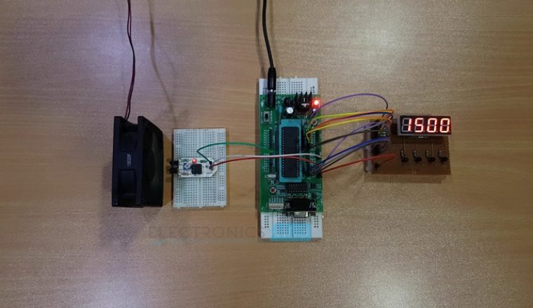
The basic principle behind the Contactless Digital Tachometer involves a simple embedded system with a sensor, a controller and an actuator. The sensor used here is Infrared (IR) transmitter – receiver pair, the controller used is the 8051 Microcontroller loaded with a compiled code and the actuator is a display device, for displaying the speed of the motor.
The sensor senses the speed of the motor without actually being in contact with it by the principle of light transmission and reflection and generates a signal. This signal is converted into an electric signal and fed to the microcontroller, which is programmed to calculate the speed in terms of number of motor revolutions in one minute. This speed is displayed on the 7-segment display.
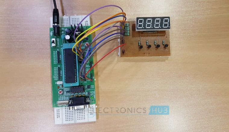
Construction and Output Video
Contactless Digital Tachometer Circuit
A Tachometer is basically used to measure angular speed of a motor. It can be mechanical device with a warm gear and spindle arrangement or an electrical device which converts the angular speed into electrical signal. The electrical tachometer in turn can be an AC tachometer or a DC tachometer.
While a conventional tachometer is a contact tachometer, which can produce erroneous results due to change in contact parameters, a Contactless digital tachometer is preferred which doesn’t requires any contact with the device whose speed is to be measured.
It basically works on the principle of retro reflective scanning, wherein a light source device like LED transmits light signal to the retro reflective target device which reflects the light, which is in turn received by the light detector.
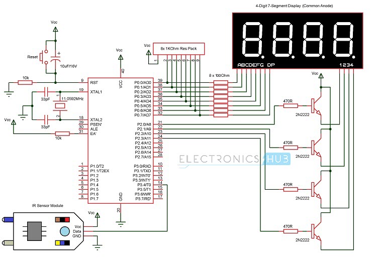
Circuit Diagram of Contactless Digital Tachometer
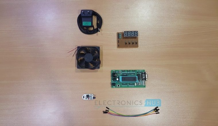
Components Required
- 8051 Microcontroller
- 8051 Development Board
- 8051 Microcontroller Programmer
- IR Sensor Module (Reflective Type)
- 4 – Digit 7 – Segment Display
- 4 x 2N2222 NPN Transistors
- 4 x 470Ω Resistors (1/4 Watt)
- 8 x 100Ω Resistors (1/4 Watt)
- If Development Board is not used, then you need
- 11.0592 MHz Quartz Crystal
- 2 x 33pF Ceramic Capacitors
- 2 x 10 KΩ Resistor (1/4 Watt)
- 10 µF Capacitor (Polarized)
- Push Button
- 1 KΩ x 8 Resistor Pack
How to Design Contactless Digital Tachometer?
Sensor Circuit Design
The sensor circuit consists of an IR transmitter and an IR receiver. An IR LED is used as the transmitter and a photo diode is used as the receiver. A reflective type of IR sensor is used in this project. In this type, the IR transmitter and receiver are placed side -by – side.
The IR transmitter circuit is very simple. The anode of the IR transmitter is connected to 5V supply and the cathode is connected to ground through a current limiting resistor of 150Ω. Thus, the IR transmitter starts emitting infrared rays.
IR receiver used in the project is a photo diode and it must be connected in reverse bias. The negative terminal or cathode is connected to 5V supply and the positive terminal or anode is connected to ground through a current limiting resistor of 10KΩ.
And finally, the output of the IR receiver is given to the comparator. The comparator compares the input from the IR receiver with a reference value (which is given through a 10KΩ Potentiometer). If the input from the IR receiver is greater than the reference value, the output of the comparator will be HIGH or else, the output will be LOW.
The following image shows the circuit diagram of the Reflective type IR Sensor used in this project.

Controller Circuit Design
The controller circuit consists of the microcontroller and its interfaces. Here, we chose AT89C52 microcontroller. Microcontroller reset circuit consists of a push button, a resistor and a capacitor with values such that the voltage at the reset pin doesn’t falls below 1.2V and the timing constant is never less than 100ms. Here, we selected a 10 KΩ resistor and 10µF capacitor.
Since the oscillating frequency of the microcontroller is 11.0592MHz, we selected the values of ceramic capacitors to be 33pF. The EA’ pin must be pulled high via a 10KΩ resistor as we are not using any external memory.
The interfacing between the Microcontroller and the IR Sensor is accomplished by connecting the output pin of the IR sensor to PORT3 pin P3.4. Next is the 4 – Digit 7 – Segment Display. The following image shows the pin out diagram of this display.

The Segment inputs of the 4 – Digit 7 – Segment display i.e. A, B, C, D, E, F, G and DP are connected to PORT0 through individual 100Ω Resistors. The Digit Selection Pins of the 4 – Digit 7 – Segment display (Dig1, Dig2, Dig3 and Dig4) are connected to the Emitter terminals of 4 2N2222 NPN Transistors. The base terminals of these Transistors are connected to PORT2 pins P2.0, P2.1, P2.2 and P2.3 through 470Ω Resistors.
Microcontroller Code
Once the circuit is designed and drawn on a piece of paper, the next step is to write and compile the code. Here, we used the Keil µVision software to write the program in C language.
Prior to writing the code, general steps needs to be followed like creating a new project and selecting the target device or the required microcontroller. Once the code is written, we saved it with .c extension and then added it to the source file group under the target folder. The code is then compiled by pressing F7 key.
Once the code is compiled, a hex file is created. In the next step, we use Proteus software to draw the circuit. The code is dumped into the microcontroller using an 8051 Microcontroller Programmer and the software associated with it.
Note: Also read the interesting post – Password Based Door Lock System using Microcontroller
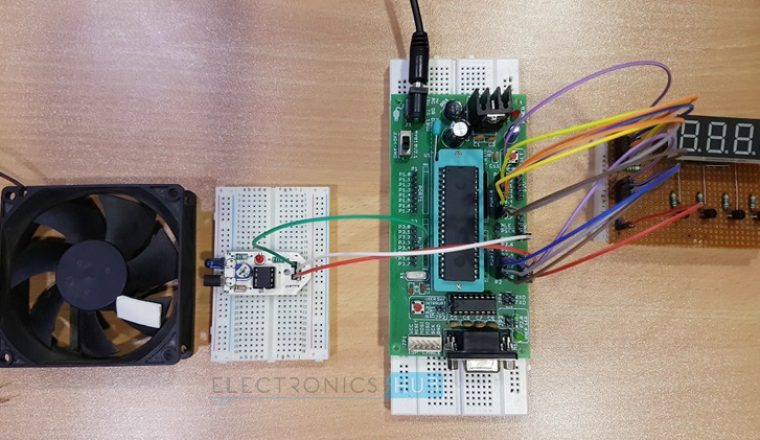
How to Operate the Contactless Digital Tachometer Circuit?
When the IR sensor is powered, the IR transmitter starts emitting IR rays. A motor is placed in front of the IR sensor, with its shafted marked with a white dot.
As the motor shaft rotates such that the white spots comes in contact with the sensor, the IR rays are reflected by the dot and falls on the IR receiver. The photo diode, which is used as the IR receiver, starts conducting whenever the IR rays are reflected.
At this point, the output of the IR sensor is given to the comparator and the output of the comparator is HIGH when the IR rays are reflected and the output of the comparator is LOW when there are no reflections. Hence, the output of the comparator is in the form of an ON-OFF pulse.
This pulse is given to the microcontroller as a timer input and the microcontroller is programmed to calculate the number of times the motor rotates in a second.
The speed of the motor is calculated by multiplying the value of final count by 60 to get the speed in revolutions per minute. This value is then displayed on the 4-digit 7-segment display.
Related Post – Digital Voltmeter using ICL7107
Applications
- The Contactless Digital Tachometer circuit can be used to calculate speed of rotating wheels, discs and motor shafts.
- This circuit can be used at places where direct contact with motor shafts or wheels is not possible to be made, as in case of vehicles and also in industrial machines.
- This circuit can be used at homes to check speed of small battery operated fans and other motor based devices.
Limitations of the Circuit
- The ICs used in this circuit are CMOS devices and are highly static, making it impossible to touch them with bare hands.
- It has limited life time due to use of battery for powering the circuit.
- Speed calculation may be affected by the varying duty cycle of the timer.

13 Responses
please provide me the code for this also
it is very helpful & benefitial for me
please post by my email
please provide me code of contactless digital tachometer using 8051 microcontroller.
please provide code for this project
I also want code for this project……..
Please provide as soon as possible……..
Please provide me embedded c code for the project
is der any other kit needed to dump the code to microcontroller????
please send code
I have been surfing online more than 2 hours today, yet I never found any interesting article like yours.
It is pretty worth enough for me. Personally, if all website owners
and bloggers made good content as you did, the internet will be a lot more useful than ever
before.
Is there any vedio lecture available on this project
provide me C language code becuase upper links are not available…..
hello could u pls provide the code for this project, its showing the code is not available when i clicked on the links provided in the above comments.
do provide the code please