The Touch ON and OFF Switch Circuit is built around a 555 timer by making use of the default properties of the Pins of the 555 Timer IC. With the help of this circuit, you can turn ON and OFF a device by simply touching the Touch Plates.
If the touch plates are placed at a convenient location, we do not require to move from our place to turn on and off the device.
And the important feature of this circuit is that you will not get any electrical shock which we sometimes get while using the normal switches, even though we are using touch plates.
As mentioned earlier, we have designed this circuit using a 555 Timer IC. The other important components are a relay module and some touch plates (we will show you how to make the touch plates used in this project).


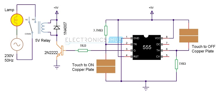
Touch ON and OFF Switch Circuit Diagram
The circuit diagram for the touch ON and OFF switch circuit is shown in the below image.
Components Required
- 1 x 555 Timer IC
- 1 x 3.3 MΩ Resistor (1/4 Watt)
- 1 x 1 MΩ Resistor (1/4 Watt)
- 1 x Bulb with holder (regular or CFL)
- 1 x 5V Relay Module (if relay module is not available, then you need the following components)
- 1 x 5V Relay
- 1 x 2N2222 NPN Transistor
- 1 x 1N4007 PN Junction Diode
- 1 x 1 KΩ Resistor (1/4 Watt)
How to make the Touch Sensor (Touch Plate)?
As the project is based on a Touch to ON and OFF the devices, Touch Plates or Touch Sensors are an important part of this project. We do not need costly or fancy touch sensors as we will show you how to make a simple touch plate for this project.
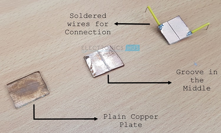
In order to make the project, we need two small pieces of Copper clad boards. Here, we have taken two 2cm x 2cm Copper clad boards.
Now, we have to make a narrow, deep cut along the centre of the boards so that we get two halves on the board without completely breaking it. This cut should completely separate the Copper on either ends.
The following image will show the bare Copper Clad board and two boards that have a groove in the middle.
You can also use the touch plate from the old toys and doorbell. Generally touch pads are made of a small carbon block mounted in silicon rubber.
When the button is pushed, this block comes in contact with the pad. Thus resistance between the two interleaved tracks is reduced.
The pads which are available in market are protected from corrosion and have very good sensitivity to detect your finger response.
When the finger is placed between the points, because of pressure and moisture in the finger resistance between these lines drops between 150k to 850k.
Circuit Design
The design of the Touch ON and OFF Switch circuit is very simple. First, the GND, VCC and RST pins of the 555 i.e. pins 1, 8 and 4 are connected to GND and 5V respectively. Pin 2 is pulled HIGH using a 3.3 MΩ Resistor and Pin 6 is pulled LOW using a 1 MΩ Resistor.
Two touch plates are connected to pins 2 and 6 as shown in the circuit diagram. In case of the touch to ON plate, one end is connected to pin 2 and other end is connected to GND. Similarly, one end of the touch to OFF plate is connected to +5V and the other end is connected to Pin 6.
Principle behind the Project
The main principle behind the project lies in the basic functionality of the pins of 555 Timer. We know that 555 Timer has 8 pins namely GND (1), Trigger (2), Output (3), Reset (4), Control Voltage (5), Threshold (6), Discharge (7) and VCC (8).
In this, Pins 2 and 6 are used in this project. Now, we see the basic working of these pins. When Pin 6 i.e. the Threshold pin is held LOW, and if Pin 2 i.e. the Trigger Pin is made LOW, the output of the 555 Timer IC will be HIGH and it stays there. This condition can be used to turn ON the appliance.
Now consider Pin 2 is pulled HIGH and if Pin 6 is made HIGH, the output of the 555 Timer IC will be LOW and it stays there. This condition can be used in our project to turn OFF the load or device.
Working of the Project
- Connect the circuit as per the circuit diagram and apply the power supply.
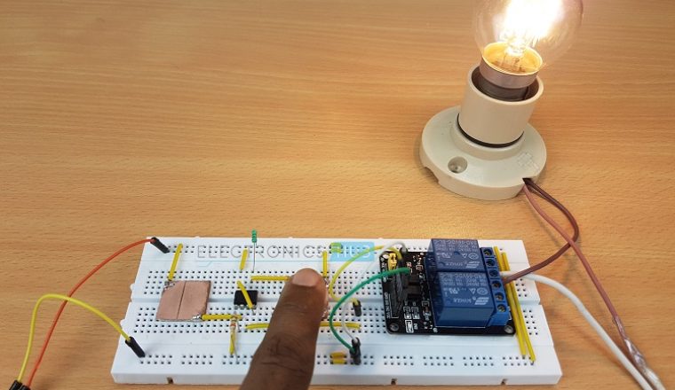
- To turn “ON” the device, touch the “ON” plate with your finger and to turn OFF the device , touch the OFF plate.
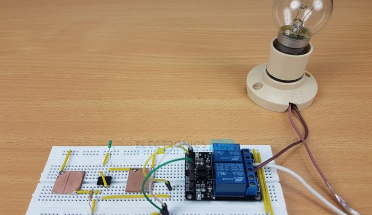
- When power supply is applied to circuit, the device connected through the relay (we have connected a light bulb) remains OFF. Now, if we observe the circuit diagram, Pin 2 is pulled HIGH and Pin 6 is Pulled LOW.
- When we touch the ON plate, voltage at Pin 2 (Trigger Pin) of the 555 IC becomes LOW. As Pin 6 is already LOW, the output at Pin 3 becomes HIGH.
- Since this is connected to the Relay Module through the Transistor, the Transistor will be turned ON and it in turn activates the Relay. As a result, the device gets switched ON.
- At this point voltage at pin 6 is zero as it pulled LOW by default and voltage at Pin 2 is HIGH.
- Now, when you touch the OFF plate, the Pin 6 is supplied with +5V for a brief time and as a result, the output of the 555 Timer IC will become LOW.
- This will turn off the transistor and also the relay. Hence, the device will be switched OFF.
- This circuit works by turning a relay to “ON” state by pressing a button and when the button is pressed again device changes to “OFF”. It is working similar to a flip-flop.
Applications
- A simple Touch to ON and Touch to OFF Switch Circuit is designed in this project using which, we can turn ON or OFF any device by simply touching the pads.
- By isolating the touch plates from the actual circuit, we can create a nice looking touch controls for our appliances.

27 Responses
Dear Sir,
I am IT Engineering Student But I could like to do some electronic Project and i am the basic of electronic circuits i need some clarification of your circuit diagram i need Component name details kindly help me to do some basic project thank u
sir, I m from electronics n instrumentation branch. plz send me some projects related to the branch having proper abstracts. thank u…
Once check the following link: https://www.electronicshub.org/electronics-projects-ideas/
sir im frm ece department. plz gide me some small projests related to communication wit proper abstract. thank you
Hi!
Please find the following link: https://www.electronicshub.org/free-project-circuits/communication/
how i can remove the losess of relay on ON & OFF time induced sparks in relay use on touch sensitive switch
i am student of electronics engineering … can u plzz guide me in choosing a medium level project with simple components only …. no Micro controllers involved
Sir…. I need a charger circuit that automatically turn off when charge is full in my mobile…
sir in kerala where we can buy the touch plate?
touch plate can be made from the simple copper u can use wires intead of plates
Cours karna chahte hai
sir, I m from electrical and electronics branch. plz send me automatic load shift fault detect by 4 relay. thank u…
Sir it is correct are not
When we execute in bread board then we get the correct output are not
sir, i want capacitive touch screen based switch board documentation or project PDF please send me…..
hi good day please i wish to join your group and also i need to submit my small project on Monday about the design of digital electronic waches with 4bits and 7 segmentsn showing all the analysis of the kmaps and boolean functions
why is a transistor used here ?
Hi, We did not use any transistor directly. It is a part of the relay circuit.
Give proper working
working of this ckt is simple 555 timer is wired as a comparator which means it compares the two voltage levels when we touch the plated at the pin 2 which is the trigger pin of ic it is connected internally to the second comparator inputs which is inverting terminal of 555 timer gets 0v from our hand which is less the 1/3vcc which will on the circuit and when we touch the plates at pin 6 threshold pin it performs reverse operation instead of getting 2/3vcc we are getting 0 volt from our hand our hand is at ground potential tahts why the circuit doesn’t response at the pin 6 i think i have tried to clered
Sir how can give 5v DC to the 555 timer plz reply me sir
simple Ranjitha dear see the pin outs of 555 timer mentioned in the datasheet 5v is 555 can be given vcc 5volt to the 8 pin of ic and 1 pin of 555 is always gnd means ground
Sir, I’m a student of class 12. I’ve taken this as my project. I’ve connected the wires according to the video tutorial but unfortunately the circuit doesn’t work. I would like to know if the breadboard holes are specific and is it necessary to insert wires in the shown holes? Also at the end, are the wires at the let end made ground? Do reply by the earliest.
Thanks!
sir i want to use this circuit in my project and can we use the raspberian in place of that relay…
use relay just
Very good Explanation , But it can more interesting in the way of understanding when Circuit diagram would given with detail.
Sir…..I have connected the circuit according to the tutorial….But…we r nt gtng output….can u reply me asap..?????
How can I help you?