In this tutorial, we will learn about Passive High Pass RC Filters, its frequency response, basic circuit of Passive High Pass RC Filters, its applications and many more.
For information on Passive Low Pass RC Filters, check out this tutorial — Passive Low Pass RC Filters.
Introduction
An Electrical filter is a circuit, designed to reject all unwanted frequency components of an electrical signal and allow only desired frequencies. In other words a filter is a circuit which allows only a certain band of frequencies.
In many applications, capacitive filters are used more than the inductive filters because the inductors will produce some stray magnetic fields and dissipates some amount of power. Not only have these drawbacks but also due to the usage of inductors in the circuit, filters becomes bulky.
In the previous tutorials we have studied basics of filters and passive low pass filter. Now let us see the operation of passive high pass RC filters.
Passive High Pass Filter
The passive High pass Filter is similar to the Passive low pass filter. When the capacitor and resistor positions are interchanged in the circuit of the low pass filter, the behavior of high pass filter is exhibited by the circuit. The capacitor is connected in series with the resistor. The input voltage is applied in series to the capacitor but the output is drawn only across the resistor.
High Pass filter allows the frequencies which are higher than the cut off frequency ‘fc’ and blocks the lower frequency signals. The value of the cut off frequency depends on the component values chosen for the circuit design. These high pass filters have many applications at high frequency ranges of 10 MHz.
The circuit of the high pass filter is shown below.
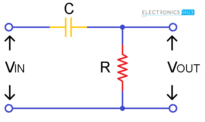
Due to this interchange of components in the circuit, the responses delivered by the capacitor changes and these changes are exactly opposite to the response of the low pass filter.
The capacitor at the low frequencies acts like an open circuit and at higher frequencies which means at the frequencies higher than the cut off frequency capacitor acts like a short circuit. The capacitor will block the lower frequencies entering into the capacitor due to the capacitive reactance of the capacitor.
We know that the capacitor itself opposes some amount of current through it in order to bind with in the capacitance range of the capacitor. After the cut off frequency the capacitor allows all the frequencies because of the reduction of capacitive reactance value. This makes the circuit to pass the entire input signal to the output when input signal frequency is greater than the cut-off frequency fc.
At lower frequencies the reactance value increases thus when reactance increases the ability to oppose the current flow through the capacitor increases.The band of frequencies below the cut off frequency is referred as ‘Stop Band’ and the band of frequencies after the cut off frequency is referred as ‘Pass Band’.
In the above circuit there is only one reactive component with resistor this shows the circuit is first order circuit.
Frequency Response of high pass filter
The response curves with respect to frequency and the capacitive reactance are given below:
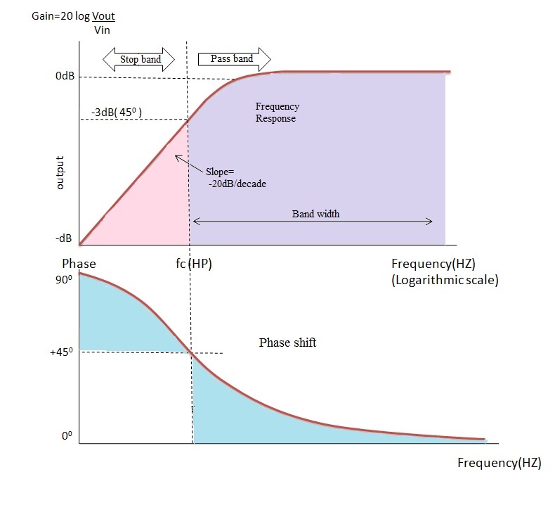
This response curve shows that the high pass filter is exactly opposite to the low pass filter. In high pass filter till the cut off frequency all the low frequency signals are blocked by the capacitor resulting in the decrease of output voltage.
At the cut off frequency point the value of the resistor ‘R’ and the reactance of the capacitor ‘X_c’are equal thus the output voltage increases at a rate of -20 dB/decade and the output signal levels are -3 dB of the input signal levels.
At very high frequencies the capacitive reactance becomes zero then the output voltage is same as that of the input voltage that is Vout = Vin. At low frequencies the capacitive reactance is infinity and thus the output voltage is zero because the reactance will block the current entering in to the capacitor.
The output of the high pass filter has the phase shift angle (ø) of +45° at cut-off frequency with respect to input signal.This shows that the output of the high pass filter is leads with reference to the input signal. At high frequencies (f > fC) the phase shift is almost zero means both input and output signals are inphase.
In ideal case, the filter will allows the frequencies after the cut off frequency point to infinity but in practical the infinity value is depends on the component values used in the design of the filter.
The time taken by the capacitor for charging and discharging of the plates with respect to the input signal results in phase difference. The resistor series with the capacitor will produce the charging and discharging effect.
The time constant of a series RC circuit is defined as the time taken by the capacitor to charge up to 63.2% of the final steady state value and also it is defined as the time taken by the capacitor to discharge to 36.8% of steady state value. This is represented by the symbol’τ’. The relation between the time constant and the cut off frequency is given as follows
Time constant τ=RC= 1⁄2πfc and ω_c= 1/τ = 1/RC.
By this it is clear that the output of the filter depends on the frequencies applied at the input and time constant.
Cut off frequency and the Phase shift
The Cut off frequency or Break point ‘fc’ = 1/ 2πfc
The phase shift (ø) = tan-1 (2πfRc)
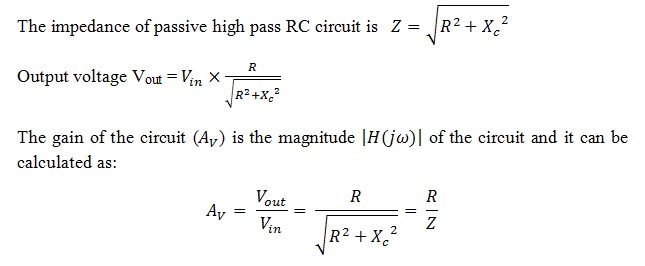
High pass RC filter output voltage and gain
High Pass Filter Example
Let us consider a high pass filter with capacitor value 82 pF and resistor value as 240 kΩ. By these values let us calculate the cut off frequency of the filter
fC = 1/(2πRC) = 1 / (2π x 240 x 103 x 82 x 10-12 ) = 8.08 kHz
Second Order Passive High Pass Filter
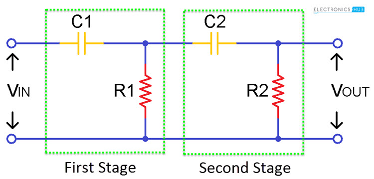
By cascading two first order high pass filters gives us second order high pass filter. Since it consists of two reactive components that mean two capacitors it makes the circuit as seconder order. The performance of this two stage filter is equal to single stage filter but the slope of the filter is obtained at -40 dB/ decade.
This is because of the cut off frequency variation. It is more efficient when compared with the single stage high pass filter because it has two storage points. For two stage filter the cut off frequency will depends on the values of two capacitors and two resistors. This is given as follows
fc = 1/ (2π√(R1C1R2C2)) Hz
Passive High Pass Filter Summary
The high pass filter allows the frequencies greater than the cut off frequency to the infinity. In practical situations infinity does not exits so this infinity value is depends on the components used in the circuit design.
The band of frequencies allowed by the High pass filter is referred as ‘Pass Band’ and this pass band is nothing but the band width of the filter. The band of frequencies attenuated by the filter is known as ‘stop band’.
The cut off frequency is calculated by using the formula ‘fc’ which is shown above. The phase shift of the output signal is leading the input signal with an angle of +45°. The output voltage will depends on the time constant and the input frequency applied to the circuit.
The distortions eliminated by the high pass filters are more accurate when compared with the low pass filters because of the high frequencies used in the circuit.
High pass RC Differentiator
For normal sinusoidal wave inputs the performance of the filter is just like the first order high pass filter But when we apply different type of signals rather than the sine waves such as square waves which gives time domain response such as step or impulse as the input signal then the circuit behaves like a Differentiator circuit.
A circuit whose derivative of the input is directly proportional to the output of the circuit called Differentiator circuit.
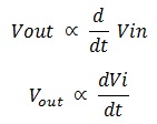
Thus when constant input is applied to the circuit the output becomes zero because the derivative of the constant tends to zero.
RC Differential circuit is shown below.
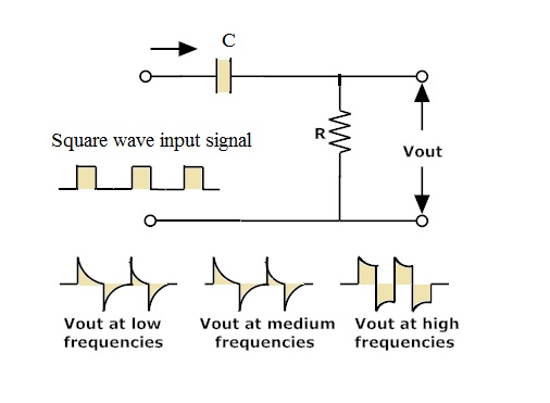
For square wave input signals the output wave form appears as a short duration pulses. For one complete cycle of input there occur two spike signals with positive and negative pulses.
In this process there will be no change in the amplitude of the output signal. If the input signal frequency increases then the width of the pulse at the output increases. The rate of the decay of the spike pulse depends on the time constant.
Applications of the High Pass Filter
- These are used in the audio amplifier circuits as a part of the high audio crossover frequencies to tweeter type signals by blocking low bass signals.
- These are used as rumble filters to block the nearby unwanted signals and pass the required signals in the loud speakers.
- These are used in the AC coupling circuits and as the differentiator circuit.
- In the mixing process at each channel strips these high pass filters are added.
- In the image processing the high pass filters are used in the process of unsharping where editing requires high boosting filter.
- In the image processing the reduction of noise can be done in either time domain or in the frequency domain. So combining with the low pass filters, these high pass filters are used to enhance, noise suppression and modify the images in the image processing.
- In the telephonic applications these are used at DSL splitters with the combination of low pass filters.

One Response
Sir can u kindly send me the download link for all tutorials so that we can download it