An inductor establishes a magnetic field when current passes through it. Most of the inductors are in the range of milli Henry (mH) or micro Henry (µH). These are available with air, ferrite and iron cores. In today’s market there are several inductors available from various manufacturers and their size varies from larger to smaller units.
Inductor values can be determined mainly by two ways, namely text coding and color coding methods. Some inductors are larger in size, thus often their values are printed on their body (name plate details).
However, for smaller inductors, abbreviation or text is used because there may not be enough room , for printing the actual value on it. Also, some inductor values can be determined by reading color on the body of inductors by comparing them with color coding chart.
Inductor Value Identification using Text Marking
In this, the value of the inductor is printed on inductor body which consists of numerical digits and alphabets. For this marking, micro Henry is the fundamental unit of measurement (even if no units are given). The following are the steps of identifying the value of inductor by using text marking method.
- It consists of three or four letters (including alphabets and numerical digits).
- First two digits indicate the value.
- Third digit is the power to be applied for the first two , this means it is the multiplier and power of 10. For example, 101 is expressed as 10*101 micro Henry (µH).
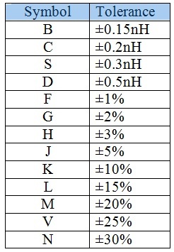
- Suffix or fourth letter or alphabet represents the tolerance value of the inductor. Suppose if this letter is K, then tolerance value is ± 10%, for J it is ± 5%, for M it is ± 20% and so on. Follow the tolerance value table given below to know each letter value.
Example for Text Marking Method
Suppose if an inductor is labeled as 223K, find the exact value of inductor.
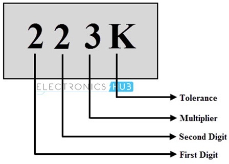
First two digits, i.e., 2 and 2 represent the first two digits of the inductor value. Third digit, 3 is the multiplier and hence it is 10^3 = 1000. Now, multiplying with first two digits we get 22000.
Now, it is to be noted that no units are given, hence this value is in micro Henry (µH). Thus the value becomes 22000 µH or 22mH.
Last letter K represents the tolerance and is equal to ± 10%.
Therefore, this is a 22000 µH or 22mH inductor with ± 10% tolerance.
Inductor Value Identification using Color Coding
The color coding system for inductors is very similar to that of resistors, especially in case of molded inductors. This color coding is in accordance with the color code table. Starting from the band closest to the one end, this color code sequence is identified. 4-band and 5-band color coding methods are described below with examples.
4-Band Inductor Color Code
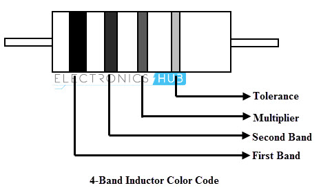
The above figure shows the 4-band inductor consisting four different color bands. Similar to the number coding, first and second color bands represents the first and second digits of the value, third color band is the multiplier and fourth band is the tolerance.
Therefore the value of inductor can be determined by reading the colors of inductor body and comparing them with color code chart. It is to be noted that the result of this color coded value is in the unit of micro Henry (µH).
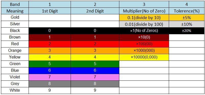
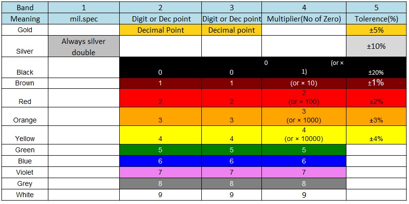
The table below shown gives the color corresponding to the numerical values for a four band inductor.
4-Band Inductor Color Code Example
Let us consider the following inductor in order to identify the value of inductor using 4-band color coding.
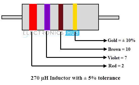
Initially, note down the tolerance percentage of the inductor which is mostly colored in gold, silver and black.
Now note the colors from other end of an inductor. In the inductor the first band is red; according to the above table the number associated with this color is 2.
Now move to second band, observe the color and note the associated number according to the color given in the table. Here, the second band is violet and its number is 7. Then the value becomes ‘27’.
Coming to 3rd band i.e., multiplier is brown in color and its corresponding number is 10.
Thus the inductor value is 27 X 10 uH = 270 uH with a tolerance rating of ±5%.
In some cases we can have this multiplier band color as gold or silver. If the multiplier is gold divide the value by ‘10’ and if the multiplier band is silver, divide the value by ‘100’.
Example 2
Consider the below inductor with band colors yellow, violet, black and silver.
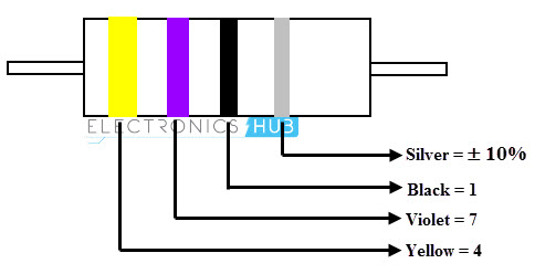
1st band yellow = 4
2nd band violet = 7
3rd band black = 1
4th band is silver = ±10% tolerance.
Thus by this we can say that the inductor is 47 uH with ±10% tolerance.
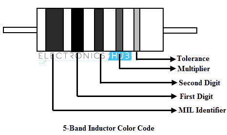
5-Band Inductor Color Code (Military Standard Inductor Color Code)
Usually cylindrical molded inductors are marked with 5 coloured bands. In this, one end of the coil consists of a wide silver band which identifies the military radio-frequency inductors. The next three bands indicate the value of inductance in micro Henries while 4th band indicates the tolerance.
The table below shown gives the color corresponding to the numerical values for a five band inductor.
These inductors consist of tolerance values from 1% to 20%. For inductance values less than 10, the second or third band is gold which represents the decimal point. Then remaining bands indicates the two significant bits, and tolerance.
For inductance values equal or more than 10, first two bands represent the significant bits, third one is multiplier and fourth one is tolerance while considering MIL band.
5-Band Inductor Color Code Example for the Values Equal or Higher Than 10 uH
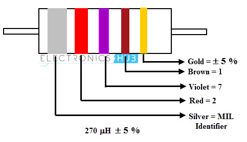
In the above figure, inductor consists of following colors:
1st band – silver (military inductor indicator)
2nd band – red (2)
3rd band – violet (7)
4th band – brown (1 or × 10)
5th band – gold (±5% tolerance)
Thus the inductor value is 270 uH ±5%.
5-Band Inductor Color Code Example for the Values Less Than 10 H
A gold band is used in either 2-band or 3-band , which indicates the decimal point. Therefore, the 4th band acts as digit instead of a multiplier. If these two bands that is 2-band or 3-band does not contain gold coloured band then the 4-band acts as a multiplier.
Consider an inductor shown in below figure.
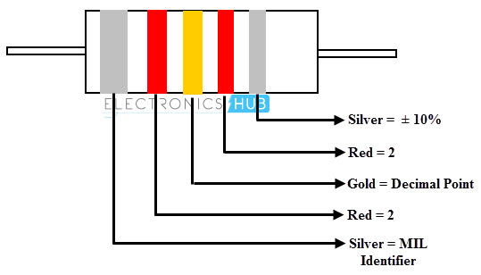
The above inductor consists of following colors
1st band – silver (military inductor indicator)
2nd band – red (2)
3rd band – gold (decimal point)
4th band – red (2)
5th band – silver (10% tolerance)
Thus, the inductor value is 2.2uH ± 10%
Surface Mount Device (SMD) or Chip Inductor Codes
Some inductors consist of color dots on surface of the device instead of bands and these are very small in size. Generally these are coded according to the top colored dot on the surface. From this top dot we have to calculate the inductor value in clockwise direction. These dots will not indicate polarity. This type of inductors measured in nano-henries.
Consider the following example:
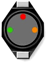
Green and red color indicates the value of inductor in nano Henries and the orange color indicates the multiplier.
Thus the value of this inductor is 52 103=52,000 nH
If only single dot is represented, the specifications of the inductor must be referred from data sheet of that particular series to that of corresponding manufacture.

RF Inductors Color Coding
These are also similar to chip inductors. These are smaller in size. Because of this size, the value of inductor is marked with a single of multiple color dots.
In a single color dot, colored dot is represented on one end or middle of the part as shown in below figure. This dot does not indicate the polarity but the value of inductance which is given on the data page of each type of inductor series.
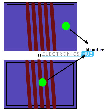
In multi-dot colored representation, inductors are marked with three color dots. These dots do not indicate the polarity. The first and second colored dots on the chip indicate the inductance in nano Henries and the third dot indicates the multiplier as shown in below.
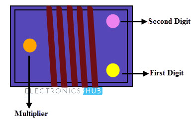
In the above figure, inductor is marked with three colors and hence the value of the inductor is given as
Yellow violet and orange = 47000 nF
Generally these RF variable inductors have the size and voltage specifications marked on the side of the inductors.
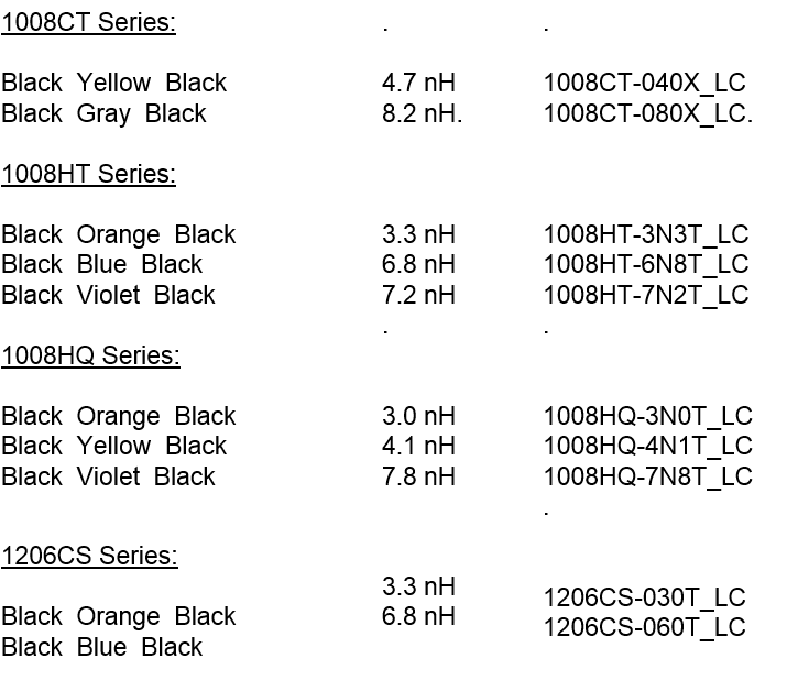
For Values Lower Than 10 nH
It is to be noted that, for inductors which are rated lower than 10nH, the third dot will not act like a multiplier. According to the series some of the inductor values are tabulated as below for inductors with coloured dots:

4 Responses
FYI: TYPO in the title here.
I am looking at an 11mm dia PC board inductor marked | 8 | with the K below it for an audio speaker filter.
What is the value here?
Fixed the typo. Thanks.
Coming to the audio inductor, not sure about it. I think ‘K’ means a tolerance of +/- 10%.
Can any expert on the topic comment about this?
Thank you so much, very helpful post.
There is a small typing mistake, I think:
the line which reads “and power of 10. For example, 101 is expressed as 10*101 micro Henry (µH).”
should read “and power of 10. For example, 101 is expressed as 10*10 micro Henry (µH).”
This post helped me understand how to determine the first and last strip. I didn’t know how to determine which colored strip is the first one, and which is the last. Other websites and tutorials draw all strips with the same width. In the real inductor in front me however, at one end the strip is bold and at the other end it is thin. Your drawings are great for that purpose. Thank you so much! Great article.