Automatic Railway Gate Control System is a simple but very useful project, which help is automatically opening and closing the railway gate upon detecting arrival or departure of the train.
In general, Railway gates are opened or closed manually by a gate keeper. The information about arrival of train for opening or closing of door is received from nearby station. But some railway crossings are totally unmanned and many railway accidents occur at these unmanned level crossings.
To avoid the human intervention at level crossings completely, we need to automate the process of railway gate control.
We have two different Automatic Railway Gate Control circuits mentioned in this article: using 8051 and AVR.
Construction and Output Video
Automatic Railway Gate Controller
Principle of Operation
The principle of operation behind the working of this project lies in the functioning of IR Sensor. A Reflective type IR Sensor is used in this project.
In Reflective Type IR Sensor, the IR transmitter and receiver are placed side by side. When there is no obstacle in front of the sensor, the IR rays transmitted by the IR Transmitter will travel undetected as there are no rays falling on the IR Receiver.
If there is an obstacle in front of the IR Transmitter and Receiver pair, the IR Rays gets reflected off from the surface of the obstacle and are incident on the IR Receiver.
This setup can be configured to detect an object like a Train and in turn can be used to switch ON or OFF the loads like motors with the help of microcontroller.
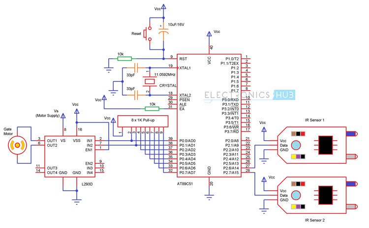
Circuit 1 Automatic Railway Gate Control using 8051
Circuit Diagram of Automatic Railway Gate Control using 8051
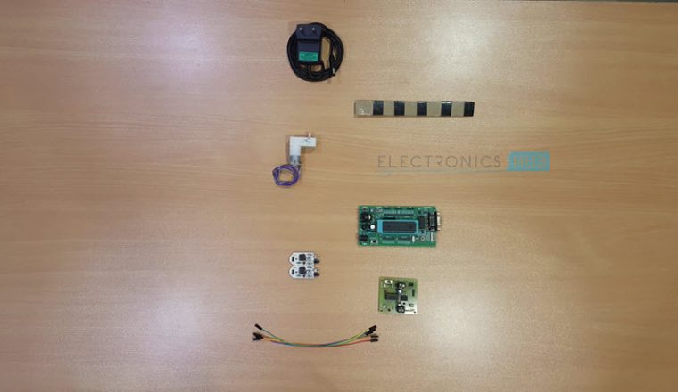
Project Components
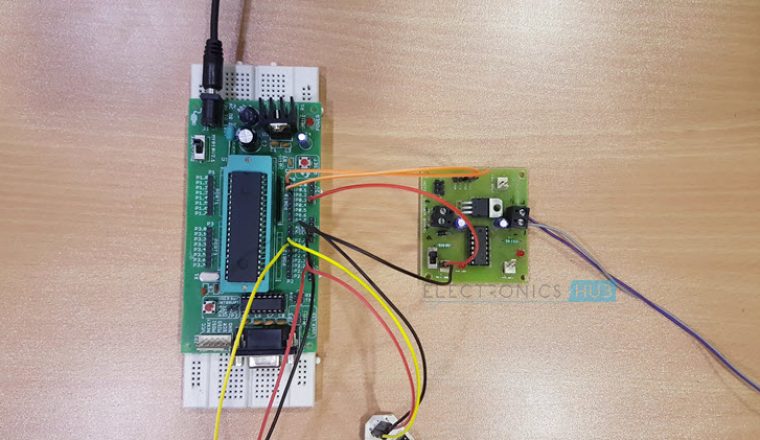
Microcontroller Section
- AT89C51 MCU
- 11.0592 MHz Quartz Crystal
- 2 x 33pF Ceramic Capacitor
- 10µF / 16V Electrolytic Capacitor
- 10KΩ Resistors x 2
- AT89C51 Programmer Board
Sensor and Load Section
- 2 x Reflective Type IR Sensor
- 2 x 1KΩ Resistor
- L293D Motor Driver IC
- Motor
Component Description
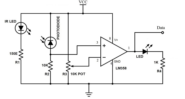
IR Sensor
- An IR sensor is used in this project to sense the arrival and departure of the train.
- An IR Sensor generally comprises of two components: an IR Transmitter and an IR Receiver. An IR Transmitter is a device that emits IR Rays.
- Similarly, an IR Receiver is a device that detects the IR Rays. Photo Diodes are the most commonly used IR Receivers.
- The following image shows the circuit of IR Sensor used in this project.
L293D Motor Driver
L293D is a motor driver IC used in this project to control the gate motor. L293D Motor Drive IC is a dual H-bridge type motor driver and is available in 16-pin Dual in-line Package.
With the help of this motor driver IC, we can control two motors at a time with both forward and reverse direction control for individual motors.
Motor drivers are generally used to drive high current drawing devices like DC Motors, stepper motors, high intensity lights, etc. They act as simple current amplifiers as their input is a low current signal usually from a microcontroller and their output is a high current signal to drive the loads.
Circuit Design
Major components of our project are 8051 microcontroller (AT89C51), Reflective Type IR Sensor, L293D Motor Driver IC and a Motor.
The mandatory connections for 8051 MCU include oscillator circuit, reset switch and EA Pin.
A crystal oscillator of up to 20MHz can be used as a source of external clock. In this project, an 11.0592 MHz quartz crystal oscillator is used. To complete the external oscillator circuit, two 33pF capacitors are used. Finally, the EA pin is pulled high using a 10KΩ resistor.
Now, let us see the actual connections required to implement the project. In that, first is the L293D Motor drive. The inputs (IN1 and IN2) to the motor driver (Pins 1 and 2) are given from Port 0 of the microcontroller.
But before connecting them, two 1KΩ resistors are used to pull the Port 0 pins high. Now, connect the motor driver input pins i.e. IN1 and IN2 to first two pins of Port 0 i.e. P0.0 and P0.1.
A motor is connected to OUT pins of the motor driver.
Finally connect two IR sensors to the microcontroller: one for detecting the arrival of the train and one for detecting the departure of the train.
So, connect the data outputs of the IR sensors to the pins P2.6 and P2.7 of the microcontroller.
Working
The working of the project is very simple and is explained here.
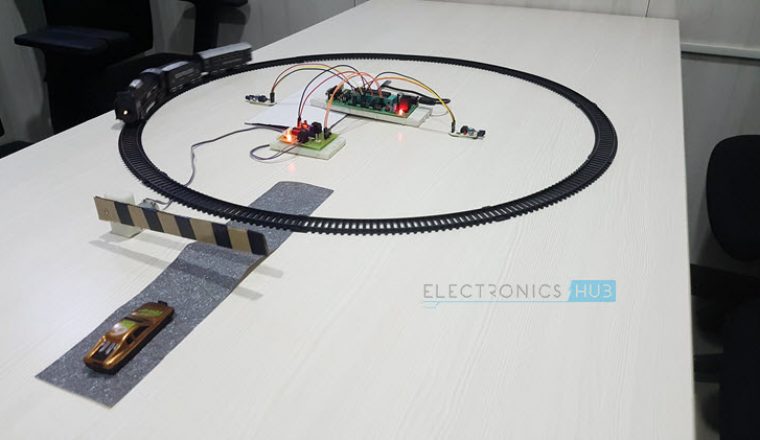
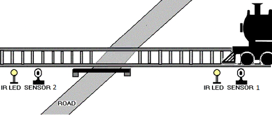
- Practically, the two IR sensors are placed at left and right side of the railway gate. The distance between the two IR sensors is dependent on the length of the train. In general we have to consider the longest train in that route.
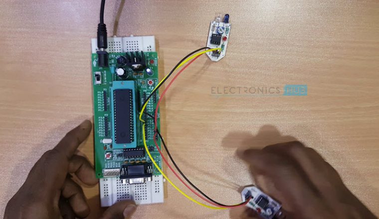
- Now we’ll see how this circuit actually works in real time. In this image, we can see the real time representation of this project.
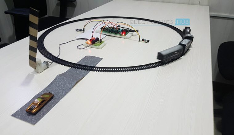
 If the sensor 1 detects the arrival of the train, microcontroller starts the motor with the help of motor driver in order to close the gate.
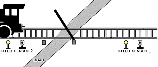
- The gate remains closed as the train passes the crossing.
- When the train crosses the gate and reaches second sensor, it detects the train and the microcontroller will open the gate.
Advantages and Applications
- An Automatic Railway Gate Control is implemented with very simple hardware and easy control.
- Human intervention at level crossings can be removed with the help of this project and many railway level crossing accidents can be prevented.
Limitations
- The system can be implemented more efficiently by incorporating more efficient sensor network.
- A combination manual wireless control and sensors based control can be used for better operation.
Circuit 2 Automatic Railway Gate Controller with High Speed Alerting System
Automatic Railway Gate Control System with High Speed Alerting System is an innovative circuit which automatically controls the operation of railway gates detecting the arrival and departure of trains at the gate.
It has detectors at the far away distance on the railway track which allows us to know the arrival and departure of the train.These detectors are given to microcontroller which activates the motors which open/close the railway gate correspondingly.
Also Read the Post: Automatic Door Bell With Object Detection
Another feature of this circuit is that it has an intelligent alerting system which detects the speed of the train that is arriving. If the speed is found to be higher than the normal speed, then the microcontroller automatically activates the alarm present at the gate.
This alerts the passengers at the railway crossing on the road about this. Also This circuit has the feature for Identification of train from other intruders i.e, animals etc .This can be implemented in manned level crossings also, as manual errors can be eliminated by automation.
Circuit Diagram of Automatic Railway Gate Controller

Circuit Operation
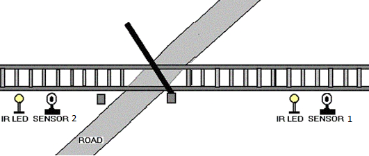
The operation of the circuit can be clearly explained as follows. Basically the circuit consists of four IR LED-Photo diode pairs arranged on either side of the gate such that IR LED and photodiodes are on either side of the track as shown in the figure below.

Initially transmitter is continuously transmitting the IR light which is made to fall on the receiver. When the train arrives it cuts the light falling on receiver. Let us assume the train is arriving from left to right, now when the train cuts the 1st sensor pair a counter is activated and when it crosses 2nd sensor pair the counter is stopped. This counter value gives the time period which is used to calculate the velocity of the train.
The sensor2 output is sent to microcontroller which makes the relay activate which causes the gate to be closed. Now when the last carriage of the train cuts the sensor4 microcontroller de-activates the relay and gates are opened.
How does the sensor know the last carriage?
Here as previously mentioned the counter value is used to calculate the velocity of the train, which means that every wheel of the carriage cuts the sensor pair within small fraction of time based on its velocity. After the last carriage is passed there is no obstacle to the sensor pair within that fraction of time hence it knows that the train has left.
One more feature of this circuit is detecting a train accurately i.e, there may be a chance that some obstacle (for e.g some animal) may cut the sensor then in such a case the counter is made to run for certain period of time (this time period is set considering the possible lowest speed of train) if the obstacle does not cut the 2nd sensor before this predefined time then this obstacle is not considered as train and gates remain opened.
Another advantage of calculating the velocity of train is, if the speed of the train crosses a limit i.e, if it is traveling at an over speed then the passengers are alerted using a by activating a buzzer.
The system basically comprises two IR LED – Photodiode pairs, which are installed on the railway track at about 1 meter apart, with the transmitter and the photodiode of each pair on the opposite sides of the track. The installation is as shown in the block diagram. The system displays the time taken by the train in crossing this distance from one pair to the other with a resolution of 0.01 second from which the speed of the vehicle can be calculated as follows:
Speed (kmph) = Distance/Time
As distance between the sensors is known and constant, the time is counted by the microcontroller and from this information, we can calculate the speed.
This circuit has been designed considering the maximum permissible speed for trains as per the traffic rule.
The microcontroller is used to process the inputs that are provided by the sensors and generate the desired outputs appropriately.
Note: Also Read the Post Automatic Washroom Light Switch

100 Responses
In automatic railway gate controller with high speed alerting system AVR microcontroller is used but the programming of microcontroller is not available in the project so I request you to provide the programming of microcontroller because I am interested in making this project.
I am interested in making this project. Can you provide the complete information of this project. I also need the programming coding of the micro controller.Thank you
His it technical seminar
yes.
here’s the short clip from this project construction video -https://www.youtube.com/watch?v=pTGWT_fr_e8
plz mail me code of ”Automatic Railway Gate Controller with High Speed Alerting System”
of this project.
did u got the source of diz project if u have den plz fwd me ma mail id is bis.mfsd@gmail.com
Plz forward the code for automatic railway gate controller
Immediately
vasundhara 66.ravi@gmail.com
Can u give send the programming code for the Automatic Railway gate control system using 8051
forward me too plss…urgent need arvindkumar430228@gmail.com
Did u get code
can i get the program code for this project bro
Can you please provide the complete information of circuit and document of multi solar tracking system and it’s project for daily use instead of prototype…. To use it for regular use.
can you help me by provide the complete information regarding the circuit and also the coding. i really interested in your project tq
pls send me the programming code of microcontroller of railway gate
plz send me the details of how the micro controller works
Can i get the programming code for this
Project please.
pls send me the programming code of microcontroller of railway gate
please send me the working programming code of microcontroller of automatic railway gate
please give the code for the project automatic railway gate controller in assembler language….please…
pls send me microcontroller programming automatic railway gate controller……
dear send me the code. here code was not given.
Code has been sent.
Sir,
I am working on this project of automatic railway gate controlling, can you please provide me the program code for this project. I need this cide very soon as possible . please forwaord that code to my email id if possible as soon .
Thank you sir in advance. My email id is rajesh_creator@live.com
plz send me code
my id is
mumar4252@gmail.com
Admin Please provide the code I am trying to work on it
sir plz send me code
i want the code too but in assembly language,,can u email the code for me?
dear send me the code. here code was not given
dear send me the code plzzzzzzzzzzzzzzzzzzzzzzzzzzzzzzzzzzzz
hey if u got the code then plz forward it to me
Sir if you got the code , please send it to me also.
Thanks
Sir if u have got the code please send to my mail id
s.varunreddy09@gmail.com
Thanks in advance
Im also very interested on this project, can provide me detail about the project? codes?
please mail me the code
Kindly send your request through contact us page or send a mail to admin@electronicshub.org
I am interested in making this project. Can you provide the complete information of this project. I also need the programming coding of the micro controller.Thank you
can you help me by providing the complete information of designing the circuit.It would be a great help.I am interested in making this project.
Please send me the design of the project,what materials are needed and how to make it.
sir please provide the source code for the microcontroller of this project send it to the mail id kamalrocksy@gmail.com without the source code this project is waste so please send it soon thanks you sir
I am interested in doing this project. please provide complete information regarding it..
Please provide complete information about the project and contact details from whom this can be available. then it can be planned to implement and save the life of road user.
please give in detail for implementation, so that life of road user can be safe.
Please send me the design of the project,what materials are needed and how to make it.
sir i am intrested to make this project.so kindly provide full information about this projects
Here we provided complete information, still if you require any additional information you can comment below.
Thank you.
sir can you send me the entire info of this project..i already send u a mail regarding this but i didn’t get any reply from u..
Complete information you can collect from here, almost we provided entire data here.
Thank you.
am interested with your idea. i wanna to know the detail.the requirement analysis, the cost also the detailed circuit and how i can implement.pls respond me as soon as possible.
sir, pls sent me the programming code
i need coding plz help 🙂
plz give me coding 🙂
plz can u provide me.with the programming code of the microcontroller and other necessary details for this.project.
Haiiii sir i am doing this project can u send me the codes
I want to know the entire operation and microcontroller code please send it to me
how will download this project
I read it its reallynice
I want to know the entire operation and micro controller code please send it to my emailid
i want code of this project..plz send it soon..
hey, i want the codes for this project plzz send it soon
I’m interested in doing this project. Could u give me the complete information including the program code
Can you please provide me with a full details of this project including the coding for the micro controller.
Would you please send me the full project details including the coding for micro-controller, I want to do this project.
plz send me assembly code of this project.
I am interested in this project. Can I get help rgarding the code of the project.My mail id is given.
can you please send me the program,i have tried on my own but i’m not able to get the output
Thankyou
Hello, plz send me a code.
Even I’m started to do this project.. .. But I’ve a doubt between is the ATMEGA16L microcontrollee is already programed as for this operation by manufacturer or we have to program this for this operation… If we’ve to program this can please send me the programing code pleaseeee
plz send da programming code. this is an emergency
sir im realy intrested in this project i really want to do this project for my smartcity can u plz send me the coding part of the project.thanku
sir
can you send me ckt. of automatic railway crossing system with component and ckt. pcb.
can you please mail me the code??
can you please mail me the complete working and microcontroller code??
Pls mail me code for railway gate controller
I want to project idea , help me
I was looking through some of your blog posts on this internet site and I conceive this web site is rattling informative ! Keep on posting . bbdgeegaeded
plz forward the programming code for automatic railway gate controller high alert system immediately plz
vasundhara66.ravi@gmail.com
sir i am really interested in this project i really want to do this project for Technical Fest can u plz send me the complete information regarding circuit and code of the project.thank you.
E-mail:ummadi.vinay@yahoo.com
sir i am really interested in this project i really want to do this project for Technical Fest can u pleaze send me the complete information regarding circuit and code of the project.thank u
Can you pls send me programming code of this project as soon as possible??
hello i want to make this railway gate monitoring system project and i want total cost for this project and when i will get if order …..please tell me thanks
Can u please mail me the source code
Pls send me the code for this project
hi, can you please mail me the code??…i really need your help..please awaljefri00@gmail.com
please email me the code for this project . thanks 🙂
Nice project….hello sir i want to make thise railway gate controller using 8051 microcontroller (AT89C51) project. Can u please send me the code for thise project.
int sensor1=2;
int sensor2=3;
int motor1=4;
int motor2=5;
void setup(){
pinMode(sensor1,INPUT);
pinMode(sensor2,INPUT);
pinMode(motor1,OUTPUT);
pinMode(motor2,OUTPUT);
}
void loop(){
C:
if(sensor1==LOW){
digitalWrite(motor1,HIGH);
digitalWrite(motor2,LOW);
delay(500);
digitalWrite(motor1,HIGH);
digitalWrite(motor2,HIGH);
A:
if(sensor2==LOW){
digitalWrite(motor1,LOW);
digitalWrite(motor2,HIGH);
delay(500);
digitalWrite(motor1,HIGH);
digitalWrite(motor2,HIGH);
delay(1000);
goto C;
}goto A;
if(sensor2==LOW){
digitalWrite(motor1,HIGH);
digitalWrite(motor2,LOW);
delay(500);
digitalWrite(motor1,HIGH);
digitalWrite(motor2,HIGH);
B:
if(sensor1==LOW){
digitalWrite(motor1,LOW);
digitalWrite(motor2,HIGH);
delay(500);
digitalWrite(motor1,HIGH);
digitalWrite(motor2,HIGH);
delay(1000);
goto C;
}
goto B;
}
}
}
You can change the delay time as your wish
Sir ,Is this code works in keilvision
Software if not please send the code in that format
Hello.. I have a question… If we want to construct sencor in real life trains than how we will measure distance on which we should construct sencor… Answer as soon as possible
Thanks
you should consider a weight sensor in order to detect the train. all you have to do is to plant the weight sensors below the track on both directions (which helps to detect both entry and exit of the train) form the railway gate (e.g. 5km). so whenever you received a signal form entry or exit sensor you can operate the gate accordingly.
P.S. the same sensors are used by Indian railways for automatic Signals.
this will work???????
Sir can I get the synopsis report of this project
you should consider signing up for our courses page in order to get the complete detail regarding this project.
it may not have a synopsis report but I am sure it has solid details regarding this project.
Can u please send me the source code I’m not able to sign up for the courses
sir i want to buy this project will u please provide me this cost and place where to buy this . I also want this program to run it thank you sir
Sir,I want to buy this project (kit).and program.
Resend to me link sir.,its not opening sir
can i get assemble language program for this project
sorry, roopal at this movement, we cant help you with that.
am interested in making this project. Can you provide the complete information of this project. I also need the programming coding of the micro controller.Thank you
What’s total cost to implement this project brother
This blog post provides a fascinating insight into the Automatic Railway Gate Control System! The integration of a high-speed alerting mechanism is crucial for enhancing safety at railway crossings. I love how it addresses both efficiency and safety, highlighting the importance of real-time monitoring. Looking forward to seeing how this technology progresses!