In the previous tutorial, we have learned about Active High Pass Filters, where a High Pass Filter is designed using Passive RC Filter along with Op-Amp Circuit. In this tutorial, we will learn about Active Low Pass Filter and understand that the transition from Low Pass to High Pass filter is merely swapping of the R and C components.
If you are looking for information on Passive Filters, then check out the following tutorials: “Passive Low Pass RC Filters” and “Passive High Pass RC Filters“.
What Is Active Low Pass Filter?
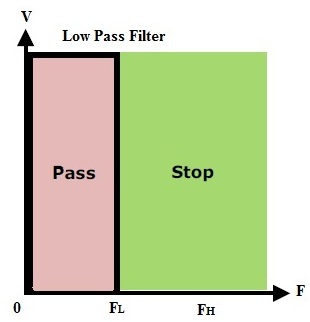
Low Pass filter is a filter which passes all frequencies from DC to upper cut-off frequency fH and rejects any signals above this frequency.
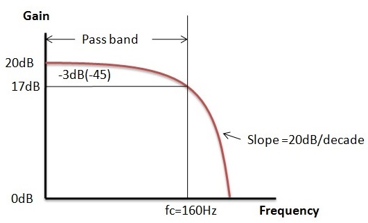
In ideal case, the frequency response curve drops at the cut-off frequency. Practically the signal will not drop suddenly but drops gradually from transition region to the stop band region.
Cut-off frequency means the point where the response drops -3 dB or 70.7% from the pass band. Transition region means the area where falloff occurs.
Stop band region means the area where the attenuation occurs mostly to the input signals. So this filter is also called as high-cut filter or treble cut filter. The ideal response is shown below.
 Rather than using the passive components alone, the Active Low Pass Filter is formed by active components like Op-Amps, FETs and transistors in combination with Passive Components. These filters are very effective when compared with the passive filters. Active filters are introduced to overcome the defects of passive filters.
A simple active low pass filter is formed by using an op-amp. The operational amplifier will take the high impedance signal as input and gives a low impedance signal as output. The amplifier component in this filter circuit will increase the output signal’s amplitude.
By this action of the amplifier, the output signal will become wider or narrower. The maximum frequency response of the filter depends on the amplifier used in the circuit design.
Active Low Pass Filter Circuit
The attenuation of the signal i.e. the amplitude of the output signal is lesser than amplitude of the input signal in the passive circuit. In order to overcome this disadvantage of passive filter, active filter is designed. A Passive Low Pass Filter connected to either inverting or non-inverting op-amp gives us a simple Active Low Pass Filter. First order active filter is formed by a single op-amp with RC circuit.
Active Low Pass Filter Schematic Diagram
A simple RC Passive Filter connected to the non-inverting terminal of an operational amplifier is shown below.
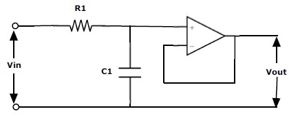
This RC circuit will provide a low frequency path to the input of the amplifier. The amplifier acts as a buffer circuit providing unity gain output. This circuit has more input impedance value. Even though the input impedance of the op-amps high below the cut-off frequency, this input impedance is limited by the series impedance which is equal to R+ 1⁄jωC.
The output impedance of the op-amp which is connected in the circuit is always low. This circuit will provide high stability to filter. The main drawback of this configuration is voltage gain is unity. Even for this circuit also the output power is high since the input impedance is low.
Active Low Pass Filter with High Voltage Gain
The above active low pass filter circuit does not provide more than unity gain. Thus,we use below circuit to provide high voltage gain.
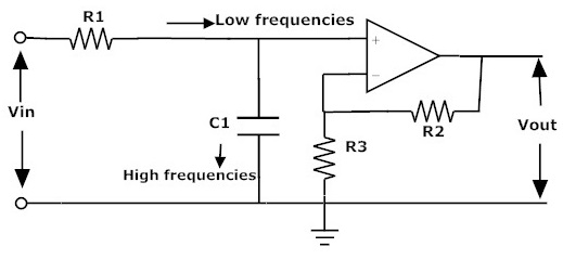
When the input signals are at low frequencies the signals will pass through the amplifying circuit directly, but if the input frequency is high the signals are passed through the capacitor C1. By this filter circuit, the output signal amplitude is increased by the pass band gain of the filter.
We know that, for non-inverting amplifier circuit the magnitude of the voltage gain is obtained by its feedback resistor R2 divided by its corresponding input resistor R3.
This is given as follows
Magnitude of the voltage Gain= {1 + (R2/R3)}
Voltage Gain of Active Low Pass Filter
We know that the gain can be obtained by the frequency components and this is given as follows
Voltage gain = V_out⁄V_in = A_max⁄ √(1+〖f/f_c 〗^2 )
Where
- Amax = Gain of the pass band = 1 + R_2⁄R_3
- f = operational frequency.
- fc = Cut-off frequency.
- Vout = Output voltage.
- Vin= Input voltage.
When the frequency increases, then the gain decreases by 20 dB for every 10 time increment of frequency. This operation is observed as below
At low frequencies that is when operating frequency f is less than cut-off frequency, then
Vout / Vin = Amax
When operating frequency is equal to the cut off frequency, then
Vout / Vin = Amax / √2 = 0.707 Amax
When the operating frequency is less than the cut off frequency, then
Vout / Vin < Amax
By these equations we can say that at low frequencies the circuit gain is equal to maximum gain and at high frequencies the circuit gain is less than maximum gain Amax.
When actual frequency is equal to the cut-off frequency, then the gain is equal to the 70.7% of the Amax. By this we can say that for every tenfold (decade) increase of frequency the gain of the voltage is divided by 10.
Magnitude of the Voltage Gain (dB): Amax = 20 log10 (Vout / Vin)
At -3 dB frequency the gain is given as:
3 dB Amax = 20 log10 {0.707 (Vout / Vin)}
Active Low Pass Filter Example
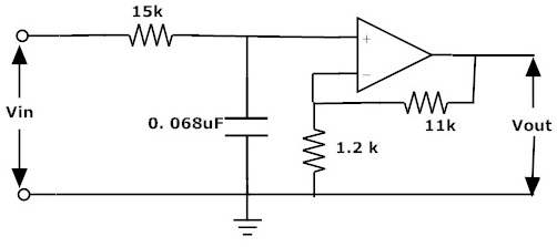
Let us consider a non-inverting active low pass filter having cut off frequency at 160 Hz and input impedance as 15kΩ. Assume that at low frequencies this circuit has a voltage gain of 10.
The gain in dB is given as 20log (Amax) = 20log (10) = 20 dB
We know that the voltage gain is given as:
Amax = 10 = 1 + (R2/R1)
Let the resistor R1 be 1.2 kΩ
R2 = 9R1 = 9 x 1.2k = 10.8 kΩ
Therefore the obtained R2 is 10.8 kΩ. Since this value does not exist we can consider the nearest preferred standard value as 11 kΩ.
By considering the cut off frequency equation we can get the capacitor value.
fC = 1/ 2πRC
By considering the C as main we can write the above equation as follows:
C = 1 / 2πfCR
Substitute input impedance value as 15 kΩ, f_C value as 160 Hz.
Therefore the C = 0.068µF.
From the obtained values we can get the active low pass filter as follows:
Frequency Response
The response of the active filter is as shown in below figure.
Second Order Active Low Pass Filter
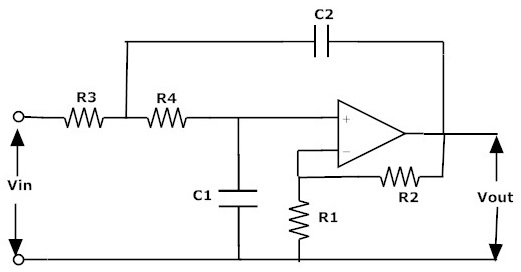
Just by adding an additional RC circuit to the first order low pass filter the circuit behaves as a second order filter.The second order filter circuit is shown above.
The gain of the above circuit is Amax = 1 + (R2/R1)
The cut-off frequency of second order low pass filter is fc = 1 / 2π√(C1C2R3R4)
The frequency response and the designing steps of the second order filter and the first order filter are almost same except the roll off of the stop band. The roll off value of the second order filter is double to that of first order filter that is 40dB/decade or 12dB/octave.These filters stop the high frequency signals more steep.
Applications Of Active Low Pass Filters
- In electronics these filters are widely used in many applications. These filters are used as hiss filters in audio speakers to reduce the high frequency hiss produced in the system and these are used as inputs for sub woofers.
- These are also used in equalizers and audio amplifiers. In analog to digital conversion these are used as anti-aliasing filters to control signals. In digital filters these are used in blurring of images, smoothing sets of data signals. In radio transmitters to block harmonic emissions.
- In acoustics these filters are used to filter the high frequency signals from the transmitting sound which will cause echo at higher sound frequencies.

2 Responses
very good
Very helpful