In the previous tutorial, we have seen about Passive Filter i.e. both Passive High Pass RC Filters and Passive Low Pass RC Filters. In this tutorial, we will learn about Active Filters and in particular, Active High Pass Filter.
As the name suggests, a High Pass Filter allows only high frequency components of a signal while restricting low frequency components. The Active part of the name is an indication that Active components like Transistors, Op-Amps etc. are used to design the filter.
If you are looking for information on Active Low Pass Filter, check out this tutorial: “Active Low Pass Filter“.
Introduction
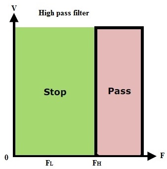
A high pass filter will allow the frequencies which are higher than the cut-off frequency and attenuate the frequencies lower than the cut off frequency. In some cases, this filter is also termed as ‘Low-Cut’ filter or ‘Base-cut’ filter. The amount of attenuation or the pass band range will depend on the designing parameters of the filter.
The pass band gain of an active filter is more than unity gain. The operation of the active high pass filter is same as passive high pass filter, but the main difference is that the active high pass filter uses operational amplifier, which provides amplification of the output signals and controls gain.
The ideal characteristics of the high pass filter are shown below.
We know that the high pass filter will pass the frequencies from cut-off frequency point to ‘infinity’ frequency which does not exist in practical considerations. Besides passive high pass filter in this active high pass filter the maximum frequency response is limited by the open loop characteristics of the op-amp.
Active High Pass Filter Circuit
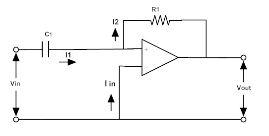
By connecting a passive RC high pass filter circuit to the inverting or non-inverting terminal of the op-amp gives us first order active high pass filter. The passive RC high pass filter circuit connected to the non-inverting terminal of the unity gain operational amplifier is shown below.
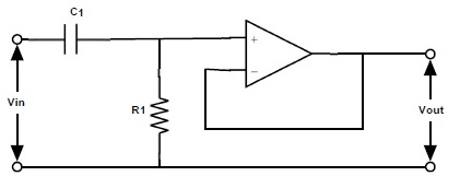
The gain Amax = 1 and cutoff frequency fc = 1/2πRC
Active High Pass Filter with High Voltage Gain
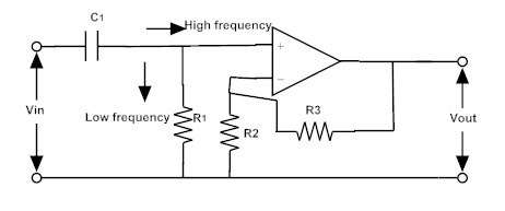
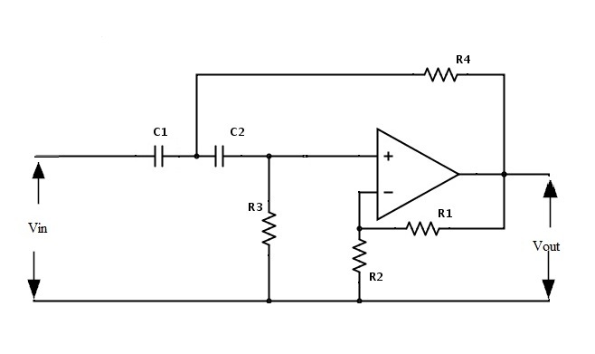
The operation is same as that of the passive high pass filter, but the input signal is amplified by the amplifier at the output. The amount of amplification depends on the gain of the amplifier.
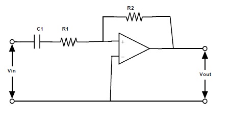
The magnitude of the pass band gain is equal to 1 + (R3/R2). Where R3 is the feedback resistor in Ω (ohms) and R2 is the input resistor. The circuit of active high pass filter with amplification is given below.
Voltage Gain Of an Active High Pass Filter
Voltage Gain Av = Amax (f/fc) / √{1 + (f/fc)²}
Wheref = operating frequency
fc = cut-off frequency
Amax = pass band gain of the filter = 1 + (R3/R2)
At low frequencies i.e. when the operating frequency is less than the cut-off frequency, the voltage gain is less than the pass band gain Amax. At high frequencies i.e. when the operating frequency is greater than the cut-off frequency, the voltage gain of the filter is equal to pass band gain.
If operating frequency is equal to the cut-off frequency,then the voltage gain of the filter is equal to 0.707 Amax.
Voltage Gain in (dB)
The magnitude of voltage gain is generally taken in decibels (dB):
Av(dB) = 20 log10 (Vout/Vin)
-3 dB = 20 log10 (0.707 * Vout/Vin)
The cut-off frequency which separates both pass band and stop band can be calculated using the below formula
fC = 1 / (2πRC)
The phase shift of the active high pass filter is equal to that of the passive filter. It is equal to the +45° at the cut-off frequency fC and this phase shift value is equated as
Ø = tan-1(1/2πfcRC)
Frequency Response of Active High Pass Filter
The frequency response curve with respect to the amplifiers open loop gain is shown below.
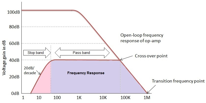
In frequency response of the active high pass filter, the maximum pass band frequency is limited by the bandwidth or the open loop characteristics of the operational amplifier. Due to this limitation, the active high pass filter response will appears like the wide band filter response.
By using this op-amp based active high pass filter we can achieve high accuracy with the use of low tolerance resistors and capacitors.
Active High Pass Filter using Inverting Operational Amplifier
We know that the active high pass filter can be designed by using either inverting terminal or the non-inverting terminal of an operational amplifier. Till now we saw the high pass filter circuit and response curves of the non-inverting active high pass filter. Now let us see the active high pass filter using inverting op-amp.
Gain derivation in Laplace form
Let us consider the inverting amplifier as shown below.
The input impedance Z1 = 1/sC1
Where s = Laplace Variable
C1 = Capacitance
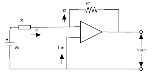
The currents flowing in the circuit are I1, I2 and Iin,
Where I1 = I2 and Iin = 0
Vin / Z1 = -Vout / R1
Vout / Vin = – R1 / Z1
Vout / Vin = – R1 / (1/sC1)
Vout / Vin = -sR1C1 = Gain
Active High Pass Filter Example
Let us consider cut-off frequency value as 10 KHz, pass band gain Amax as 1.5and capacitor value as 0.02 µF
The equation of the cut-off frequency is fC = 1 / (2πRC)
By re-arranging this equation we have R = 1 / (2πfC)
R = 1/ (2π * 10000 * 0.02 * 10-6) = 795.77 Ω
The pass band gain of the filter is Amax = 1 + (R3/R2) = 1.5
R3 = 0.5 R2
If we consider the R2 value as 10KΩ, then R3 = 5 kΩ
We can calculate the gain of the filter as follows
Voltage Gain for High Pass filter | Vout / Vin | = Amax * (f/fc) /√[1 + (f/fc)²]
Av(dB) = 20 log10 (Vout/Vin)
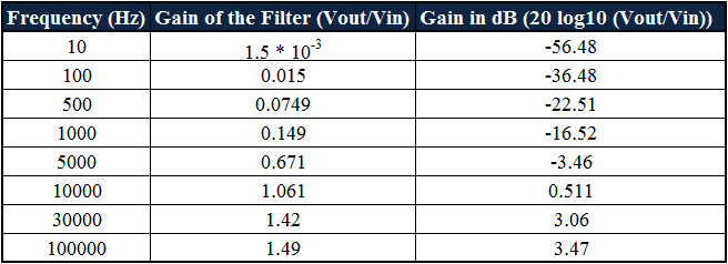
By using this equation let us tabulate the responses for the range of frequencies to plot the response curve of the filter. These responses are assumed as 10 Hz to 100 KHz.
Bode-plot
To analyse the circuit frequency response this bode plot is used. It is nothing but a graph of the transfer function of linear, time variant verses frequency. This is plotted with the log frequency axis. It consists of mainly two plots; one is magnitude plot and the other is phase plot.
The magnitude plot will express the magnitude of the frequency response i.e., gain and the phase plot is used to express the response of the frequency shift.
The frequency response bode-plot according to the values which are tabulated above is given below:
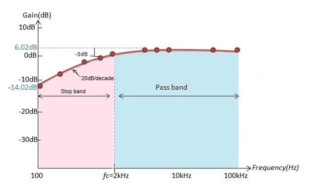
According to the values calculated, at frequency 10 Hz the gain of the filter obtained in dB is -56.48. If we increase the value of frequency to 100 Hz the obtained gain is -36.48 dB and at frequency 500 Hz the gain of the filter is -22.51 dB.
At frequency 1000 Hz gain in dB is -16.52. By this we can say that if frequency increases the gain of the filter increases at the rate of 20dB/decade.
Till the cut-off frequency 10 KHz the gain of the filter increases but after the cut-off frequency the gain reaches maximum value and it is constant.
Second Order High Pass Filter
Second order active filter frequency response is exactly opposite to the second order active low pass filter response because this filter will attenuate the voltages below the cut-off frequency. The transfer function of the second order filter is given below
Vout(s) / Vin(s) = -Ks² / s² + (ω0/Q)s + ω0²
Where K = R1/R2 and ω0 = 1/CR
This is the general form of the second order high pass filter.
Second Order Active High Pass Filter Circuit
The designing procedure for the second order active filter is same as that of the first order filter because the only variation is in the roll-off. If the roll-off of the first order active high pass filter is 20dB/decade, then roll-off of the second order filter is 40 dB/ decade.
It means the twice of the value of the first order filter. The circuit of second order filter is shown below.
The gain of the filter is 1+ R1/R2 and the equation of the cut-off frequency is fc = 1/ 2π√R3R4C1C2
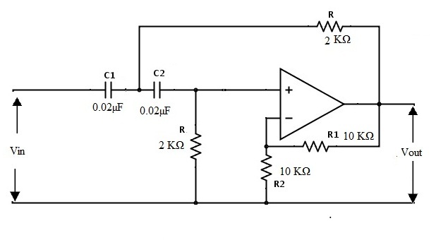
Second Order Active High Pass Filter Example
Let us design a filter with cut-off frequency 4 KHz and the delay rate in the stop band is 40 dB/decade. As the delay rate in the stop band is 40 dB/decade we can clearly say that the filter is second order filter.
Let us consider the capacitor values as C1= C2 = C = 0.02µF
The equation of the cut-off frequency is R = 1/ 2πfC
By re-arranging this equation we have R= 1⁄2πfC
By substituting the values of cut-off frequency as 4 KHz and capacitor as 0.02µF
R = 1.989 KΩ = 2 KΩ.
Let the gain of the filter is 1+ R1/R2 = 2
R1 / R2 = 1
R1 = R2
Therefore we can take R1 = R2 = 10 KΩ
Thus the obtained filter is shown as below.
Higher Order High Pass Filters
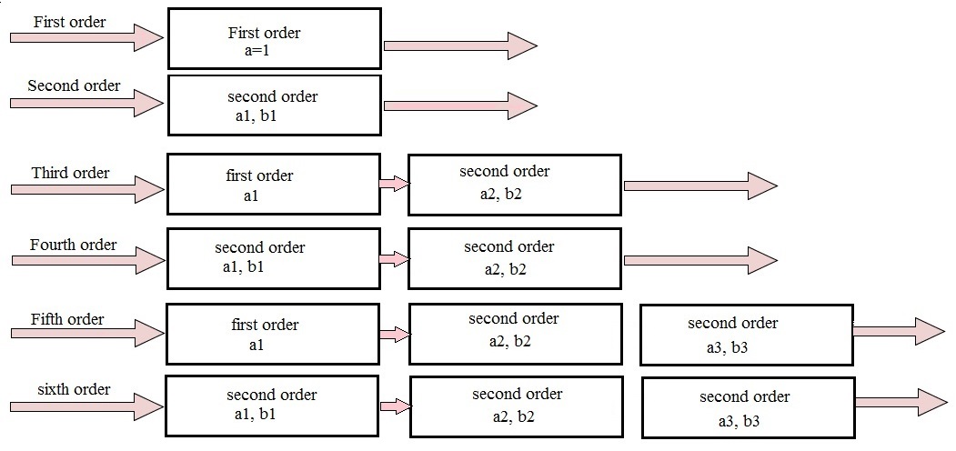
By cascading first order filter with second order filter , we can obtain the third order filter. When we cascade two second order filters we can get the fourth order filter. Like this with the help of first order and second order filters we get the higher order filters.
With the increase in the order of the filter,the difference between actual stop band and theoretical stop band increases. But the overall gain of the higher order filter is equal because we already saw that the resistors and capacitors which determine the frequency response values will be same.
This cascading order is shown below.
Applications of Active High Pass Filters
- These are used in the loud speakers to reduce the low level noise.
- Eliminates rumble distortions in audio applications so these are also called are treble boost filters.
- These are used in audio amplifiers to amplify the higher frequency signals.
- These are also used in equalizers.
