Often, electrical generators are removed from the service and connected back to the power system during variations of the load, emergency outages, maintenance, etc. Every time before reconnecting the generator to the system, it must be synchronized by aligning the electrical parameters (voltage, frequency, etc.) of the power system network. An improper synchronization can affect the healthy power system and results in electrical and mechanical transients that can damage the prime mover, generator, transformers and other power system components. In this tutorial, we will learn about Synchronization of Generators.
What is Synchronization of Generators?
The process of connecting a generator to a power grid or another generator (a healthy or running power system) by matching the electrical parameters such as voltage, frequency, phase angle, phase sequence, and waveform of alternator (generator) is called Synchronization of Generators.
A Generator cannot deliver power to electric power system unless its voltage, frequency and other parameters are exactly matched with the network.
When a generator connects to a grid or other generators without synchronization, differences in voltage or phase can create surges that threaten the system’s integrity. Electrical surges may damage both the generator and the grid. This can lead to power outages and high repair costs.
In power plants, multiple generators operate together to supply large volumes of electricity to the grid. Synchronization allows these generators to work as one unit by balancing loads and distributing energy evenly.
Similarly, grid-connected generators require synchronization to provide power from decentralized sources (such as wind and solar). Synchronization helps integrate these sources into the grid efficiently and maintaining a stable power supply despite fluctuations in renewable energy generation.
Backup generator systems also use synchronization to prevent service interruptions during power outages. By synchronizing with the main power supply, backup generators can take over without delay when the main supply fails, then seamlessly return control when the primary source resumes.
Hence, effective synchronization plays a key role in the stability and reliability of the power supply. Synchronization is accomplished by controlling the exciter current and the engine speed of the generator.
What is the Need for Paralleling Generators?
In most commercial power plants, several small units (generators) supply the power rather than single large unit. This is called as Parallel Operation of Generators. Here are some reasons for preferring this practice:
- Reliability: Several small units are more reliable than a single large unit. This is because, even if one alternator fails, other alternators are still active and hence the whole system will not be shutdown.
- Continuity of Service: In case of periodic maintenance, break-down, or repairs of one alternator, that unit must be shut down and removed from service. Since the other machines are operating in parallel, there is no interruption to power supply to the load.
- Load Requirements: The load requirements in the central power station changes continuously. During light-load periods, only one or two generators operate to supply the load demands. During peak-load demands, additional alternators are connected in parallel to meet the demand.
- High Efficiency: Generators run most efficiently when they are loaded at their rated values. Due to the operation of few generators at light-loads and more generators at high peak loads, none of the generators are over-burdened and all of them operate efficiently.
- Expanded Capacity: As the demand for electric power is increasing continuously, utility companies have been increasing the physical size of the power generating plants by adding more generators. The simplest way to increase capacity is connect new generators in parallel with the existing generator equipment.
Key Conditions for Synchronization of Generators
For successful generator synchronization, four primary parameters (or conditions) must align: voltage, frequency, phase sequence, and phase angle.
Voltage
The first condition, voltage matching, requires the generator’s output voltage (usually, the RMS Voltage) to align with the grid or the other generator’s voltage (again, the RMS Voltage). Differences in voltage between the generator and grid can result in unequal power distribution.
For instance, a generator with a higher voltage will attempt to push more power into the system, which can stress and potentially damage both the generator and grid infrastructure.
Conversely, a generator with lower voltage may not supply sufficient power to the grid, causing instability.
To avoid these issues, operators measure and adjust the generator’s excitation system to maintain a voltage level that matches the grid’s requirements, typically around 230 volts for residential systems or 400 volts for commercial grids.
Frequency
Next important condition is frequency matching, which involves adjusting the generator’s frequency to match the grid’s frequency, typically either 50 Hz or 60 Hz depending on regional standards.
Frequency differences can lead to significant issues such as phase misalignment (which has a huge impact on power stability). For example, a generator running at a higher frequency than the grid could cause power surges, while a lower frequency may result in interruptions.
Frequency synchronization relies on a governor system, which controls the generator’s speed to maintain a steady frequency output. Improper matching of frequency results in high acceleration and deceleration in the prime mover that increases the transient torque.
Phase Sequence
Each generator and grid system operates using a three-phase system, commonly labeled L1, L2, and L3. The generator must follow the same phase rotation as the grid, meaning that L1 of the generator must align with L1 of the grid, and so on.
If the phase sequence differs, the connection will result in a short circuit or other serious electrical issues. To achieve this, operators verify the sequence using phase-sequence meters before connecting the generator. Advanced synchronization systems can automatically detect phase sequences.
Phase Angle
Finally, phase angle matching completes the conditions for successful synchronization by aligning the generator’s phase angle with that of the grid. Phase angle refers to the timing between the voltage waves of the generator and the grid.
Ideally, the phase angle difference should remain as close to zero as possible when connecting the generator. Any significant angle difference creates power oscillations.
Operators use a synchroscope or other synchronizing instruments to monitor and adjust the phase angle. This can be observed by comparing the occurrence of zero crossing or peaks of the voltage waveforms.
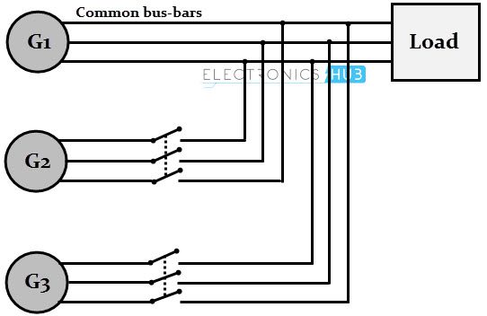
Procedure for Connecting Generators in Parallel
When the above-mentioned conditions are fulfilled, the generators are said to be synchronized. The actual process of synchronization or paralleling generators includes the following steps:
- Consider that Generator-1 is supplying power to the bus bars at rated voltage and frequency.
- Now, we have to connect an incoming Generator-2 in parallel with Generator-1 for the first time. By increasing the speed of this generator, its frequency is varied and hence the speed is adjusted till it matches with bus bar frequency (or the frequency of Generator-1).
- By varying the field rheostat, we can vary the voltage of the Generator-2. Hence, it is adjusted till the voltage matches with bus bar voltage.
- The three voltages generated by the Generator-2 must be in phase with the respective voltages of the bus bar (or Generator-1). This is achieved by maintaining the same phase sequence and frequency of Generator-2 with bus bar or Generator-1.
For achieving these relationships, synchronizing lamps technique is used, which we will learn in the next section.
Different Methods of Generator Synchronization
There are different methods for the Synchronization of Generators. The primary purpose of these techniques is to check and implement all four conditions that we discussed above. In power systems, operators may use either manual or automatic synchronization, depending on the application and the level of complexity.
Manual synchronization uses basic equipment like analog meters and synchronizing lamps, while automatic methods rely on advanced devices such as synchroscopes and synchronizing relays. Each approach has its advantages and challenges, making them suitable for specific scenarios in power generation.
Manual Synchronization
Despite the advances in technology, manual synchronization still remains a widely used method for synchronization of generators, especially in smaller power generation setups or backup systems.
This process relies on human operators who visually monitor electrical parameters and make adjustments manually. Operators use meters to measure voltage and frequency and synchronizing lamps to check the phase relationships.
In a typical manual synchronization procedure, an operator first starts the generator and adjusts its speed to match the frequency of the grid or another generator. The operator then adjusts the generator’s excitation system to achieve voltage matching.
Once the voltage and frequency align, the operator checks the phase angle using synchronizing lamps. If these parameters align, the operator connects the generator to the grid by closing the breaker at the correct moment.
What are Synchronizing Lamps? Synchronizing lamps help operators visually confirm phase alignment. These lamps connect across the terminals of the generator and grid and light up when a difference exists in phase or frequency.
Lamp Dark Method (Three Dark Lamps Method)
The following figure shows the circuit for lamp dark method. The main generator (G1) is connected to the load supplying rated voltage and frequency. Now the new generator (G2) must be connected in parallel with G1.
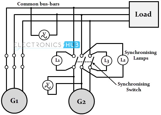
Three lamps (each of which is rated for generator terminal voltage) are connected across the switches of the G2. From the figure, it is clear that the moment when all the conditions of parallel operation are satisfied, the lamps should be off or dark.
To synchronize the G2 with bus bar, the prime mover of the G2 is driven at speed close to the synchronous speed decided by the bus bar frequency and number of poles of the alternator.
Now the field current of the G2 is increased till voltage across the machine terminals is equal to the bus bar voltage (by observing the readings on voltmeters).
If lamps go ON and OFF concurrently, it indicates that the phase sequence of G2 matches with bus bar. On the other hand, if they turn ON and OFF one after another, it indicates an incorrect phase sequence.
By changing the connections of any two leads of G2 after shutting down the machine, the operator can change the phase sequence.
The frequency difference between G2 voltage and bus bar voltage, determines the ON and OFF rate of these lamps. Hence, the job of the operate is to reduce the rate of flickering to match the frequency. This is possible by adjusting the speed of alternator by its prime mover control.
When all these parameters are set, the lamps become dark and the operator can close the switch to synchronize G2 with G1.
Drawback of Lamp Dark Method
The main disadvantage of this method is that rate of flickering only indicates the voltage difference between the G2 and the bus bar. It doesn’t provide any information on the generator frequency in relation to bus bar frequency.
If the bus bar frequency is 50Hz, the rate of flickering of lamps is same when the frequency of the G2 is either 51 or 49 Hz, as the difference in these two cases is 1Hz.
The three lamps method is not preferred nowadays due to less accuracy and manual operation.
Two Bright and One Dark Lamp Method
The two-bright-one-dark method is another way to check synchronization by arranging the lamps differently. In this approach, the operator watches for a pattern where two lamps glow brightly, and one lamp remains dark. It is useful in finding whether the generator frequency is lower or higher than the bus bar frequency.
The following image shows the connections for this method. Here, the lamp L2 is connected across the center pole, whereas the lamps L1 and L3 are connected in a transposed manner.
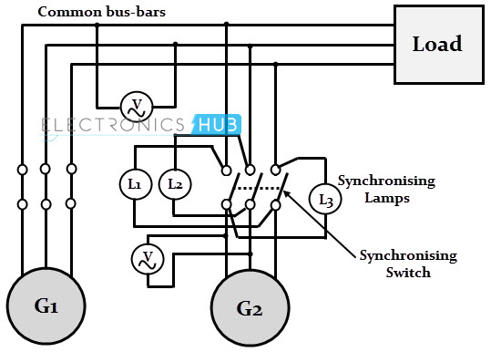
The voltage condition checking is similar to the previous method. After this, the lamps glow bright and dark one after another. The sequence in which the lamps become dark and bright determines if the frequency of G2 is lower or higher than the bus bar frequency.
If the sequence of becoming bright and dark is L1 – L2 – L3, it indicates that the G2 frequency is higher than the bus bar frequency. Hence, the operator has to reduce the G2 speed by controlling the prime mover.
On the other hand, if the sequence of flickering is L1 – L3 – L2, it indicates that G2 frequency is less than that of bus bar. Hence, the speed of the G2 is now increased. The operator closes the synchronizing switch at the instant when lamps L1 and L3 are equally bright and lamp L2 is dark.
The disadvantage of this method is that the we cannot check the correctness of phase sequence. However, this requirement is unnecessary for permanently connected generators where checking of phase sequence is enough to be carried out for the first time of operation.
Automatic Synchronization
Larger or more complex power systems use automatic synchronization, which is faster and more accurate than manual synchronization. This method uses specialized equipment like automatic synchronizers and synchroscopes to match the generator’s electrical parameters with that of the grid’s.
Synchroscope Method
It is similar to the two bright and one dark lamp method and indicates whether the alternator frequency is higher or lower than the bus bar frequency. A synchroscope is used for better accuracy of synchronization and it consists of two pairs of terminals.
Older Synchroscope methods were manual, where an operator check the scope and adjusts the speed of the alternator. Modern synchronization equipment automates the whole synchronization process with the use of microprocessor-based systems that avoids manual synchroscope observations.
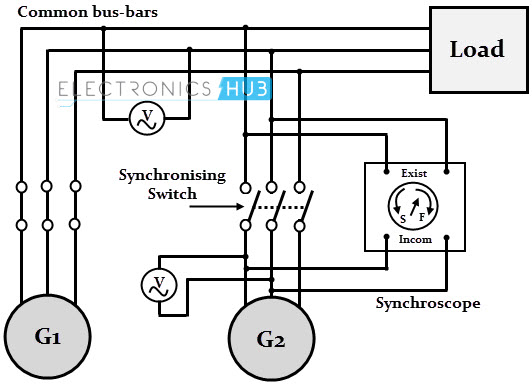
Synchroscope has two sets of terminals. The first set marked ‘existing’ has to be connected across the bus bar terminals or to the existing generator and other set of terminals marked ‘incoming’ has to be connected across the new generator.
The synchroscope has a circular dial with a hinged pointer that is capable of rotating in clockwise and anticlockwise directions.
After checking the voltage, the system checks the synchroscope. The direction of the rotation of the pointer indicates the difference of frequency between the incoming generator and the bus bar.
When the dial rotates clockwise, it signals that the generator’s frequency is higher than the grid’s frequency. A counterclockwise rotation shows a lower frequency. When the pointer remains steady at the twelve o’clock position, the generator’s phase angle aligns with the grid’s.
The system makes appropriate corrections to control the speed of the alternator so that the pointer remains steady. This stable position indicates the right moment to connect the generator to the grid.
Synchronizing Relays
Another type of automatic synchronization of generations is achieved using synchronizing relays. These relays continuously monitor the generator’s electrical parameters to detect any differences from the grid or connected generator systems.
Each relay contains sensors that measure voltage levels, tracking the phase angle, and measure frequency. Once all parameters align, the relay activates the generator breaker to complete the connection.
Types of Synchronizing Relays
- Single-Function Relays: As the name suggests, single-function synchronizing relays primarily handle a single parameter—either voltage, frequency, or phase angle. In a small backup generator system, a single-function relay might monitor only voltage alignment. It signals the generator to connect once voltage levels match. However, single-function relays have limitations in dynamic environments where multiple parameters change frequently. If the frequency or phase angle shifts unexpectedly, single-function relays lack the capability to adjust other parameters.
- Multi-Function Relays: If you want real-time control over multiple parameters, then multi-function synchronizing relays are the way to go. These relays continuously track each parameter and make necessary adjustments to optimize synchronization. Multi-function relays often include additional features like automatic voltage control, which fine-tunes the generator’s voltage in response to grid fluctuations. These relays can also initiate automatic shutdowns in case of faults.
Conclusion
A beginner’s tutorial on the concept of Synchronization of Generators, the need for synchronization or paralleling of alternators (or generators), conditions to be met for proper synchronization, different methods of synchronization along with their advantages and disadvantages.

25 Responses
it is very nice information and useful to our project.so thank you!!!
Thank you.
Is it any method of synchronizing the two single-phase generators with AVRs?
I’d there a need to synchronize generators if they are ran by the same power unit
Very good explanation.. thank you
Thanq it’s very useful information to me.
Thanks a lot
I have cleared my concept after reading this great explaination…
Wonderful explanation Full fill & help full for project.
Very usefull can understand in a short period of time
Very good explanation.. thank you
Very useful topic. I would be appreciated if you could give me the name of auto-synchrocheck in the market used for small generator used in critical power application like data center or some other ordinary cases like shopping mall.
May I get any video for synchronization process explaining that, why pointer rotating clockwise / anti-clockwise, slow or fast rotating ? and for that cases what is my action (raise/lower speed/voltage) ?
Very good
Very nice, thanks for given useful information.
Very nice, thank given useful information
well illustrated.
is very clear information,
very good article,nice explanation
That good information, thanks d
If phase sequences are incorrect then by synchroscope method how will it be reflected?
Nice explanation,, helpful for all
Tnq
So nice
Excellently explained with well drawn diagrams
Thanks for your good explanation
Well explained in simplest word thats a double skill