PID controllers are most widely used automatic industrial controllers. In process industries, most of the control loops (typically 90-95 percent) are of PID type.
These controllers receive inputs from sensors, meters, etc. and depending on PID control function they deliver output control signals to the controlled or manipulating devices such as relays, actuators, etc.
These are the most common form of feedback systems and become a standard tool for precise control applications.
Let us discuss PID controller components, working and its tuning methods.
What is Feedback Control System?
Before beginning our discussion on PID controllers, let us define a few key terms.
- The process: It is the system to be controlled
- The process variable: It is the quantity to be measured and controlled
- Sensor or transmitter: It is a device that measures process variable
- The Controller: It decides the control variable in order to bring the process variable as close as to the set point.
- Final Control Element: It is a device that directly manipulates the manipulating variable to control over the process.
- Manipulating Variable: It is the quantity which can be directly altered to control over the process variable.
For the sake of illustration, consider that desired power has to be generated from the generator by adjusting turbine steam as shown in figure below.
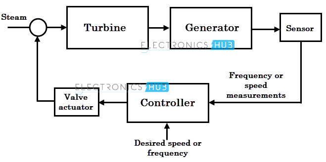
In this case, the process is the entire generating system that consists of turbine to which steam has to be controlled, and a generator in which delivered power is maintained at a particular frequency.
Here the process variable is the measured quantity that we wish to control in the process, so it is the frequency or speed measurements. This is measured by using sensors as shown in figure.
To maintain a certain frequency or speed, here steam input to the turbine is controlled, so the steam flow is known as the manipulating variable, because by manipulating this quantity, we can take control over the process variable. This is controlled through a control valve, which is also called as a final control element.
In this, the most critical component in generator control system is the controller. It is designed in such a way that it interpret process variable from sensor and then decide how far open the control valve (and hence manipulating variable) so as to maintain a process variable at the desired value.
What is PID Controller?
A PID controller is a three-term controller that has proportional, integral and derivative control coefficients. It is named after its three correcting terms and its sum produce a control action for manipulating variable.
It measures the output of a process and controls the input by maintaining the output at a desired value (also called as set point). The most common example of PID controller is controlling temperature in many industrial applications.
In the above example if we use a PID algorithm as a controller for whole process, then we can call it as a PID control system. A PID controller can be implemented by analog circuitry or by microprocessor technology.
Practically, most of modern PID controllers are designed based on microprocessor technology.
Different manufacturers use different PID equations. There are three most commonly used PID equations, namely parallel, ideal or ISA and series or interacting PID equations.
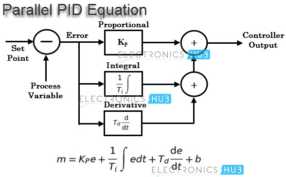
In a parallel equation, each action (i.e., Proportional P, integral I or derivative D) occur in separate terms of the equation and a sum is produced with the combined effect. In this each parameter is independent of others.
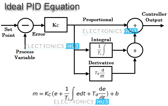
Another version of PID equation also exists to provide very functionality. This is called as the ideal or ISA equation. In this, gain constant Kp is distributed to all terms in it so that changes in Kp affects all other terms in the equation.
The third version of PID equation is the series or interactive equation that basically derived from the characteristics of pneumatic and analog electronic circuits.
In this, the change in Kp affects all three actions just as an ideal PID equation, but the difference is that both integral and derivative constants have an effect on proportional action.

So before dealing with any real-time PID controllers, or PID control algorithms in any controller like PLCs or PACs, first we have to consider the type of equation used for implementing PID control function, before we go through its tuning process.
The three main reasons of PID controller to become an important control include an earlier record of success, simplicity in use and wide availability.
How a PID Controller Works?
As discussed above that a PID controller uses the control algorithm as three modes, i.e., proportional + integration + derivative.
The proportional term applies appropriate proportional changes for error (which is the difference between the set point and process variable) to the control output. In fact, many control applications work quite well with only proportional control.
The integral term examines the process variable over time and offset of set point and then corrects the output if necessary.
Derivative control monitors the rate of change of process variable and accordingly changes the output when there are unusual changes.
Each parameter of three control functions is adjusted by user to get the desired performance from the process. Let us see the individual responses of PID controllers.
Proportional, P Action
It is the most common of all industrial process control action. It calculates the difference between the process variable signal and the set point signal, which is called as an error.
It is the measure of how far a process variable is deviating from a set point and it can be calculated either as SP – PV or PV – SP depending on whether controller will be direct acting or reverse action.
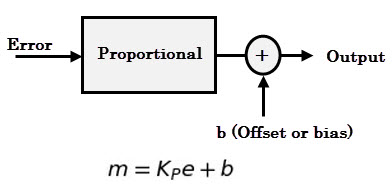
This direction of action is determined by the process, sensing device and final control element. The output of the proportional controller is the multiplication of error signal by a constant (also called as gain).
In some cases, bias is also added to the p-control output as shown in figure below.
If the error is greater, the greater will be the controller output and as long as the error remains, it continues to generate corrective effort. As the error is zero, it produces zero output (if no bias is added at output).
If the controller gain is increased, it moves the output so rapidly for any given change in PV or SP.
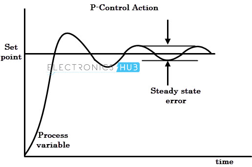
However, too much control gain can result unstable control system. As a result, there exists a steady state error between the set point and the process variable.
Integral, I Action
It is the process of accumulating the process variable value as the time progress. Integral action decides how fast to move the output. This is mainly used to eliminate steady state error of the system.
In this, controller output depends on the integral of error signal over time. It doesn’t be used alone, but mostly it is used along with proportional control. If the integral term is added to the control equation, then the equation becomes
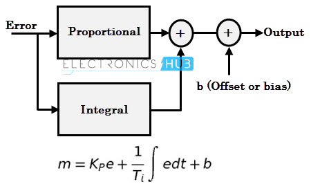
Here the integration symbol indicates that the controller will accumulate multiple products of error over a small time dt.
When an error signal appears, the controller acts such that the proportional control signal returns the process to the desired control point and it is fast acting and immediate.

If there is any deviation between set point and process variable, an addition corrective signal is supplied by the integral control mode function till steady state error becomes zero.
At this situation, controller holds the previous value to maintain final control device such that zero steady state error is achieved. The steady state performance is improved by decreasing the integral gain Ki.
Often the above proportional plus integral equation is written without bias term b, because the presence of integral action makes it unnecessary.
Most of the industrial process controllers are designed to operate proportional plus integral control to achieve an improved steady state response.
Derivative, D Action
This action senses the rate of change of process variable and then applies the corrective action at a proportional rate of change. It looks at how fast the process variable changes per unit time and takes action proportional to its rate of change.
This is also called as anticipatory action because it moves the control valve in such a direction as to counteract the rapid change of process variable.
The output of derivative action is the product of derivative constant and the rate of change of error with respect to time.
It must not be used alone because of rapid start of control output that can result extremely large rate of change of output, even for a small error change.
Most of the cases, it is used along with proportional plus integral control or with only proportional control. If this term is added to PI controller then the equation becomes

In order to avoid the extreme increase of control output for sudden change of set points, many PID controllers offer derivative response based on the rate of change process variable only, rather than error (SP-PV or PV-SP).
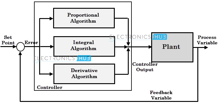
By combining all three actions describe above, a PID action is obtained. It is the most often used controller in many industrial applications.
This type of controller gets the set point from the user, and gets the process variable from various sensing devices or transmitters.
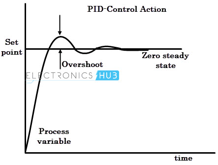
Depending on the parameter setting in PID equation (i.e., Kp, Ki and Kd), it produces the control output to make the correction promptly and accurately to the set point value. The response curve for the PID controller is shown in figure.
PID Tuning Method
The determination of corresponding PID parameter values for getting the optimum performance from the process is called tuning. This is obviously a crucial part in case of all closed loop control systems.
There are number of tuning methods have been introduced to obtain fast and acceptable performance.
The steps involved in these methods include experimental determination of the dynamic characteristics of the control loop and estimating the controller tuning parameters that produce a desired performance for the dynamic characteristics determined. Some of these PID tuning methods are given below.
Trial and Error Method
This is the simple method of tuning a PID controller. Once we get the clear understanding of PID parameters, the trial and error method become relatively easy.
- Set integral and derivative terms to zero first and then increase the proportional gain until the output of the control loop oscillates at a constant rate. This increase of proportional gain should be in such that response the system becomes faster provided it should not make system unstable.
- Once the P-response is fast enough, set the integral term, so that the oscillations will be gradually reduced. Change this I-value until the steady state error is reduced, but it may increase overshoot.
- Once P and I parameters have been set to a desired values with minimal steady state error, increase the derivative gain until the system reacts quickly to its set point. Increasing derivative term decreases the overshoot of the controller response.
Zeigler-Nichols Method
It is another popular method for tuning PID controllers. Ziegler and Nichols presented two classical methods for determining values of proportional gain, integral time and derivative time based on transient response characteristics of a given plant or system.
First Method
- Obtain a unit step response of the plant experimentally and it may look‘s’ shaped curve as shown in figure below. This method applies, if obtained response exhibit s-shaped curve for unit step input otherwise it cannot be applied. This curve can also be obtained by dynamic simulation of the plant.
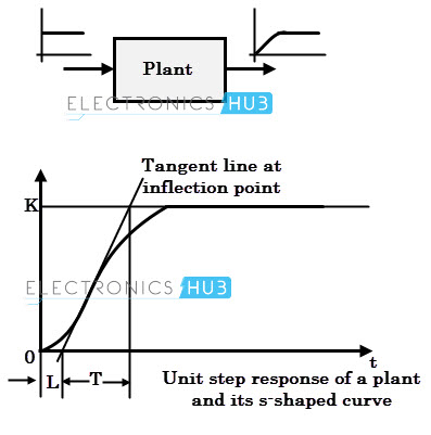
- Obtain two constants, delay time L and time constant T by drawing a tangent line at the inflection point of the s-shaped curve.
- Set the parameters of Kp, Ti, and Td values from the table given below for three types of controllers.
Second Method
- It is very similar to the trial and error method where integral and derivative terms are set to the zero, i.e., making Ti infinity and Td zero.
- Increase the proportional gain such that the output exhibits sustained oscillations. If the system does not produce sustained oscillations then this method cannot be applied. The gain at which sustained oscillations produced is called as critical gain.
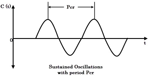
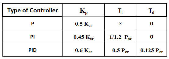
- Once the sustain oscillations are produced, set the values of Ti and Td as per the given table for P, PI and PID controllers based on critical gain and critical period.
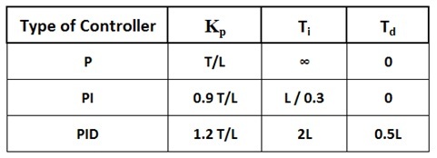
Image Credits:
- PID Controller: pacontrol.com

5 Responses
Wow it is nicely good
nicely explained everything.
what is l on the second table?
What is process reaction curve in PID turning
I think you have mixed the tables, they should switch places (on the Z-N method)