Electrical filter is a circuit, designed to reject all unwanted frequency components of an electrical signal and allows only desired frequencies. In other words a filter is a circuit which allows only a certain band of frequencies. The main applications of the filters are at audio equalizers and in sensitive electronic devices whose input signals should be conditional. These filters are mainly categorized into 2 types. They are Active filters and passive filters.
Filters and Capacitive Reactance
Passive Filters
Passive filters do not contain any amplifying elements just they are made up of Resistor, Capacitor and inductors (passive elements). These filters will not draw any additional power from the external battery supply. The Capacitor will allow the high frequency signals and inductor allows low frequency signals. Similarly inductor restricts the flow of high frequency signals and capacitor restricts the lower frequency signals. In these filters output signal amplitude is always less than the amplitude of the applied input signal.The gain of passive filters is always less than unity.This shows that the gain of the signals are cannot be improved by these passive filters. Due to this the characteristics of the Filters are affected by the load impedances. These filters can work at higher frequency ranges nearly at 500 MHz also.
Active Filters
Active filters contain amplifying elements such as Op-Amps, Transistors and FET’s (active components)in addition to the passive elements (Resistors, Capacitors and Inductors). By using these filters we can overcome the drawbacks of Passive filters. Active filters will depend on external power supply because it will amplify the output signals. Without any inductor element these can achieve the resonant frequency that is the input impedance and output impedances are nullified by each other. In following year’s inductor less filter design is made. Because inductors dissipate some amount of power and generates stray magnetic fields. Not only have these problems, but also due to inductor the size of the active filter increases. So, due to these reasons the use of inductors in active filters is reduced.
Some of the advantages of Active filters
- The combination of op-amps, resistors, capacitors, transistors and FETs gives an integrated circuit which in turn reduces the size and weight of the filter.
- The gain of an Op-amp can be easily controlled in the closed loop form. Due to this reason the input signal is not restricted.
- These are applicable in Butterworth filters, Chebyshev and Cauer filters.
The main drawback in active filters is the operational frequency range is less. In many applications the operational frequency range of active filters is maximized to 500 kHz only. The active filters must require D.C power supply. When compared with the passive filters these active filters are more sensitive. The outputs may disturb even due to the environmental changes also.
The filter is a sensitive circuit and in which the output components are only frequency terms. To analyze the filter circuit the frequency domain representation is the best one. This representation is as shown below.
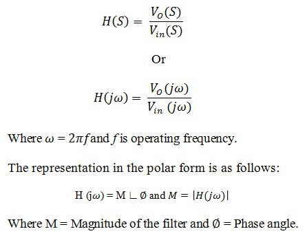
The magnitude of the filter M is called as the gain of the filter. Magnitude is generally represented in dB as 20log (M).
One of the important characteristic of the filters is cut-off frequency. It is defined as the frequency which separates both pass band and stop band in frequency response. Pass band is the range of frequencies that are allowed by the filter without any attenuation. Stop band is defined as the band of frequencies that are not allowed by the filter.
Filters are classified based on the frequency of signals that they allowing through them. There are four types of filters they are Low Pass Filters, Band Pass Filters, High Pass Filters and Band Stop Filters. Due to the usage of high speed op-amps and approximate values of the components the characteristics of ideal and practical responses are nearly equal.
Low Pass Filter
Low Pass Filters will pass the frequency signals less than cut-off frequency ‘fc’. Practically a small range of frequencies will pass even after the cut-off frequency range. The gain of the filter will depend up on the frequency. If the input signal frequency increases then, gain of the filter decreases. At the end of the transition band the gain becomes zero. This is as shown below.
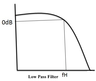
Fig: Low Pass1
Where dotted line indicates the ideal filter characteristics and continuous line indicates practical filter characteristics.
Applications of low pass filters are in sound system that is in various types of loudspeakers. To block the harmonic emissions these low pass filters are used in radio transmitters. These are also used at DSL splitters in telephone subscriber lines.
High Pass Filter
They will pass the frequencies after the cut off frequency ‘fc’. In practical case a negligible frequencies below the cut off range is allowed by the filter. This is as shown below.
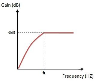
Fig: high pass1
The combination of high pass filter with low pass filter forms Band pass filter. Applications of the high pass filters are at RF circuits and are also used in DSL splitters.
Band Pass Filter
The name of the filter itself indicates that itallows only a certain band of frequencies and blocks all the remaining frequencies. The upper and lower limits of the band pass filter depend on the filter design. Practical and ideal characteristics of band pass filter are shown below.
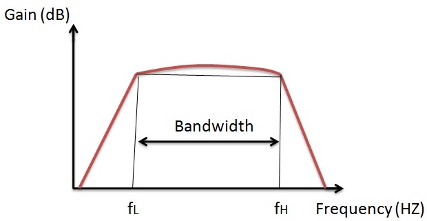
Fig: band pass1
Applications of band pass filters are at transmitter and receiver circuits. These are mainly used to calculate the sensitivity of the receiver circuits and to optimize the signal to noise ratio.
Band Stop Filter
These are also called as Band rejection or band elimination filters. These filters stop only a particular band of frequencies and allow all other frequencies.The frequency limits of the filter depend on the filter design.The dotted line indicates the ideal case where as a continuous line indicates the practical case. It has two pass bands and one stop band.
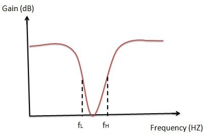
Fig: band stop1
Applications of band stop filters are at instrument amplifiers.
Ideal filters frequency response
Now let us see the ideal response of different filters. Here fL indicates the lower cut-off frequency and fH indicates the higher cut-off frequency.
Ideal characteristics of Low pass filter
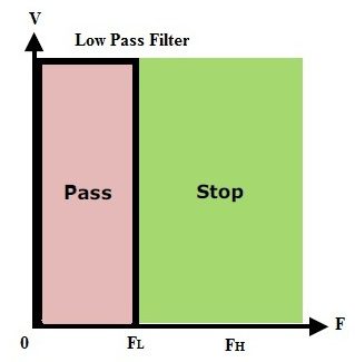
Fig: low pass2
This response shows that the low pass filter will allow the signals up to lower cutoff frequency and stops the frequencies higher than the lower cutoff frequency.
Ideal characteristics of High pass filter
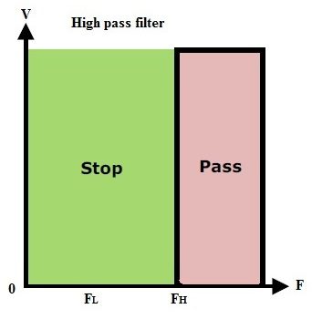
Fig: high pass2
This shows the high pass filter will allow the frequencies greater than the higher cut off frequency and stops the frequencies lesser than the high cut off frequency.
Ideal characteristics of Band pass filter
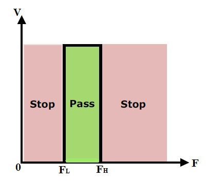
Fig: band pass2
This response shows that the band pass filter will pass the frequencies between the lower cutoff region and higher cut-off region only. It stops the frequencies which are lesser than the lower cutoff frequency and also stops the frequencies greater than higher cut-off frequencies.
Ideal characteristics of Band stop filter
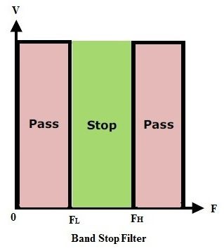
Fig: band stop2
The above figure shows that the frequencies which are greater than the lower cut off frequency and the frequencies which are lower than the higher cut off frequency are not processed.
Capacitive Reactance
When the Resistor is connected in series with the capacitor forms RC circuit. In RC circuit the capacitor will charge from the D.C supply voltage and when supply voltage is decreased, eventually the capacitor also discharges by reducing its storage charge. Not only at the time of the D.C supply even in the case of A.C supply also according to the supply voltage level the capacitor will charge and discharge continually.
But due to internal resistance there will be some attenuation in the flow of the current through the capacitor. This internal resistance is called as Capacitive Reactance. ‘X_C’Indicates the Capacitive Reactance and it is measured in Ohms same as that of the resistance.
When the frequency is varied in the capacitive circuit according to the amount of frequency change this capacitive reactance value also changes. The electrons flow from one plate to the other plate causes the current flow in the circuit. But due to the movement of electrons the frequency level varies. When the frequency through the capacitor increases the capacitive reactance value decreases and when frequency through the capacitor decreases the capacitive reactance value increases. Thus, by this we can say that the capacitive reactance is inversely proportional to the applied frequency level. This shows that the capacitor connected in the circuit is dependent on supply frequency. This phenomenon is called complex impedance.
Capacitive Reactance Formula
Xc = 1/(2π1c)
Where Xc = Capacitive Reactance
π = 3.142
f = Frequency in Hz
c = Capacitance in Farads (F).
Capacitive reactance Example
Let us consider two frequencies to observe the capacitive reactance phenomenon. Let f_1=1kHzandf_2=10kHz and the capacitor c = 220nF.
At first frequency level
X_C= 1/2πf1c = 723.4Ω
At second Frequency level:
X_C= 1/2πf2c= 72.34Ω
This shows clearly that with the increase of frequency the reactance decreases.
Capacitive Reactance Vs Frequency
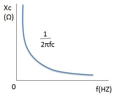
From the above frequency verses capacitive reactance plot we can observe that when the frequency is zero the reactance value reaches to infinity this shows the phenomenon of the open circuit. When the value of the frequency increases exponentially the reactance value decreases. When frequency reaches to infinity the reactance value at nearly zero this gives us closed circuit behaviour.
Voltage Divider concept
We have already studied the voltage divider concept in resistors topic and we know that the voltage divider circuit is able to produce the output voltage which is a fraction of the input voltage.
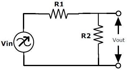
VOUT = VIN x (R2 / (R1 + R2))
By replacing the resistor R2 with a capacitor C in the above circuit the voltage drop across the two components changes with the input frequency because reactance of the capacitor varies with the frequency.Now the output voltage across the capacitor depends on the input frequency. Using this concept we can construct passive low and high pass filters by replacing one of the resistors with a capacitor in a voltage divider circuit.
Capacitor behaviour in Low Pass Filter
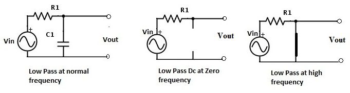
For the Low pass filter the resistor R2 is replaced by the capacitor C1. At normal frequency the circuit is as shown in the above figure. When the frequency is zero the reactance value is very high which is nearly equal to infinity. At this condition circuit acts as an open circuit. When frequency is very high the reactance value reaches to zero and the circuit acts as a closed circuit. Both of these behaviour are shown in the above figure.
Capacitor behaviour in High Pass filters
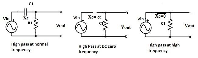
For the High pass filter the resistor R1 is replaced by the capacitor C1. From the above figure it is clear that at normal frequency the circuit acts like a high pass filter circuit. Initially at the zero frequency value the circuit behaves like an open circuit. When frequency increases the reactance will decreaseexponentially. At some point the frequency reaches to infinity level thus, it affects the reactance to reach the zero state. These circuit behaviors are shown in the above figures.
