Mosquito repellents like coils, mats, liquid vaporisers, creams are often used at various places. However they are prone to be fatal and can cause harm to human beings. For instance, mosquito repellent creams and oils can cause adverse affects on the skin like allergic reactions. Coils, mats can produce toxic fumes when heated and cause breathing trouble, whereas liquid vaporisers can also produce fumes when heated.
For efficient results without any side effects, the most optimum solution is building a simple electronic circuit with minimal components which can produce output so as to repel the mosquitoes. In plain words, this article is going to describe a simple mosquito repellent circuit.
Principle Behind Mosquito Repellent Circuit:
Human beings can hear sound in the range of 20 Hz to 20 kHz. Sound of any frequency above 20 kHz is termed as ultrasonic sound. Several animals like cats, dogs, insects, mosquitoes have the feature of being able to hear this ultrasonic sound. In mosquitoes, this feature is attributed to the presence of sensory structures in their antenna.
Usually ultrasound is transmitted by male mosquitoes and received by female mosquitoes. However after breeding, female mosquitoes generally avoid the ultrasound and this fact can be used to produce ultrasound in a range similar to that produced by male mosquitoes and repel away the mosquitoes. The ultrasound produces a stress on the antennae of the mosquitoes and repels them away.
In other words, a simple circuit is designed which can produce ultrasound in the frequency range of 20 kHz to 38 kHz, which can scare away mosquitoes.
Circuit Diagram of Electronic Mosquito Repellent Circuit:
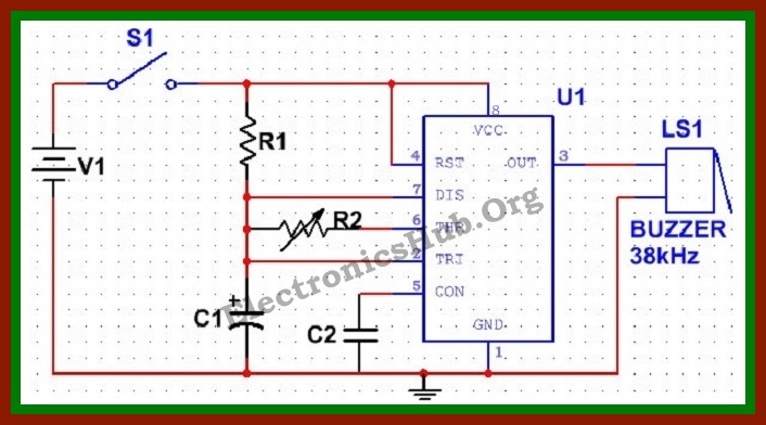
The most common form of Astable multivibrator is 555 Timer IC. It is basically an 8 pin IC with the following pin description:
- Pin1 – Ground pin, which is directly connected to the negative terminal of the battery.
- Pin2- Trigger Pin. It is an active low pin. The timer is triggered when signal at this pin is less than one third of supply voltage. For astable operation this pin is connected directly to pin no.6
- Pin 3 – It is the output pin.
- Pin 4 – It is the reset pin. It is an active low pin. It is usually connected to positive rail of the battery.
- Pin 5 – It is the control pin and is seldom used. For safety purpose, this pin is connected to ground through a 0.01microFarad ceramic capacitor.
- Pin 6 – It is the threshold pin. The timer output is back to its stable state when voltage at this pin is greater than or equal to two-third of supply voltage. For astable operation, this pin is shorted to pin 2 and connected to pin 7 using a resistor.
- Pin 7 – It is the discharge pin and provides the discharge path for the capacitor.
Components Required
- 555 timer
- An electrolyte capacitor of 0.01 micro Farad
- A ceramic capacitor of 0.01 micro Farad
- A resistor of 760 Ohms
- Another resistor of 1.5 K
- piezo buzzer
- A SPST switch
- A 5 V battery
Mosquito Repellent Circuit Design:
The basic idea behind developing the circuit is to use a buzzer to produce ultrasound. The buzzer is driven by an oscillator circuit. Here, we are using a 555 Timer based astable multivibrator circuit as the oscillator circuit.
Designing the circuit involves designing an astable multivibrator circuit. Generally, frequency of output signal produced by a 555 astable multivibrator is given by:
F = 1.44((Ra+Rb*2)*C)
Here Ra is the value of resistor between pin 7 and Vcc, Rb is value of resistor between pins 7 and 6 and C is value of capacitor between pin 6 and ground.
Let C = 0.01 microFarad
F = 38 kHz
Let Duty Cycle, D = 60% (It is not possible to get 555 timers to produce signal with 50% duty cycle.
This gives,
Ra = 1.44(2D-1)/(F*C)
And Rb=1.44(1-D)/(F*C)
Substituting values of C, F and D, we get
Ra = 0.758 K Ohms, i.e. 758 Ohms and Rb = 1.52 K Ohms
Thus, we can use a resistor of 760 Ohms and another resistor of 1.5 K. Here a potentiometer of 1.5 K is used.
Theory Behind the Circuit:
- A multivibrator is an electronic circuit producing a pulsed output signal. Generally multivibrators are classified based on the nature of stability of output.
- A multivibrator with one stable state is known as monostable multivibrator and is used as a pulse generator.
- A multivibrator with no stable state is known as an astable multivibrator and is used as an oscillator.
- A multivibrator with two stable states is known as a bistable multivibrator and is used as a Schmitt Trigger.
Here we are mainly concerned about Astable multivibrator. Astable multivibrators do not require any external triggering and hence can be used as oscillators. They are realized using transistors, operational amplifiers or ICs.
Mosquito Repellent Circuit Operation:
Once the switch is closed, the 555 timer gets the power supply. As per the inner circuit, initially the capacitor voltage will be zero and hence voltage at threshold and trigger pin will be zero. As the capacitor charges through resistors Ra and Rb, at a certain point voltage at threshold pin is less than the capacitor voltage. This causes a change in timer output. The capacitor now starts discharging through resistor Rb, i.e. the discharge pin and continues so until the output voltage is back to the original. Thus the output signal is an oscillating signal with frequency 38 KHz. The output from this astable multivibrator circuit drives a 38 KHz piezo buzzer, producing ultrasound at regular repetitions. On varying the value of potentiometer, the output frequency can also be varied.
Applications of Mosquito Repellent Circuit:
As described, this circuit can be used as a mosquito repellent. By certain modifications and changes in the value of resistors and capacitor, the circuit can also be used as other insect repellent. Further, it can also be used as a simple buzzer alarm circuit.
Mosquito Repellent Circuit Limitations
- It requires a lot of frequency setting.
- Ultrasound signals travel at an angle of 45 degrees from the source. In case of any obstacles in the path, the signals get reflected or diverted.
- It shows effect for lesser mosquito population.
Note: Also read the post – Air Flow Detector Circuit

37 Responses
we want latest mini and major project ideas in ece field
Once visit the following link: https://www.electronicshub.org/ece-projects-ideas/
this is a really nice & useful project
does this mosquito repellent work??
this project is not working! please fix the diagram. we need this for our final project. thanks in advance
this is really good project
bt i have a doubt…according to u this repalent can only scar away the female mosquitos
wat about the male one….????
male mosquito take only plants as their food that does not bite any human beings
yah,its good Rishi because the world fighting against female mosquitoes in order to disappear a MALARIA deseas.
You don’t know male mosquitoes don’t bite us ??
due to rainy season ,this is very useful to us
I tried but didnt get 0.01 Micro farad conductor
Then plz what i have to do
Resourceful site…with gratitude
It is very nice and usefull circuit as it does not produced pollution.
what should i do for other insects like bees??
plz help me ,i am not getting 0.01microfarad electrolyt conductor..
Go to the shop and ask for ceramic capacitor instead. Value 103. I.e 10*10^3 pf. I have designed this circuit long ago and it worked. With slight modification, it can be used as alarm, buzzer, harmonium etc. By just adjusting resistance values. Go for all ceramic capacitors as to make the circuit more compact to fit inside a match box. I used a soap case to enclose everything – circuit, battery and speaker/piezzo tweeter. Use potentiometer for variable resistor and a knob to mount it on soap case.
Do ultrasonics doesn’t cause any harm to humans?
is it’s work
Anybody tell me the working range of thi circuit.
Where do you find a 38kHz piezo buzzer?
this is really nice and useful project
nice project..i need the flow chart and blog diagram for the circuit, i tried doing them but am a little confused
can we do any further adjustments like automation,battery backup..??please let me know
Is tis project working….?
how long distance will cover for that frequencies produced by the circuit ?
May I know the range of this circuit in avoiding mosquitos
Can u say the working range of the device and the idea is super
Where do you get 38kHz piezo buzzer
This circuit doesn’t work
how to overcome the limitation of this repeller
sir, how can i use for other insects? also what are those insects please help me?
i need sooner.
greetings, i want to ask regarding the piezo buzzer.. the output frequency is 38khz .. so is there any piezo buzzer can give output around the expect 38khz?
Hi, can you breakdown what is contain in the IC please?
or rather can you breakdown the circuit diagram please.
it wil sacre away the mosquitos of 45 degree but they wil be roming 360 degree. cant it be modified to scare away the mosquitos more than 45 degree
GOOD i’m try it, an it work thank u brother engr.
You didn’t provide the complete value of components, like voltage of capacitor and wattage of resistance, etc.
Excellent content.Its a great idea ti repel female mosquitoes .Because male mosquitoes are not dangerous at all .Only female mosquitoes are responsible for all mosquito borne diseases.