Nowadays, door bells are very common in every house. We daily observe different types of door bells are available in the market and they produce different types of music depending on their functionality. One can design their own door bell using simple electronic components. This article explains a simple circuit that produces “ding dong” sound using 555 timer.
Ding Dong Bell Sound Generator Circuit Principle:
This circuit mainly consists of two 555 timer ICs. First timer IC is operated in astable mode and the frequency of the second is modulated by the first timer. For that, output pin of first IC is connected to the 5th pin of second IC. The first timer IC is operated at a frequency of 1Hz.
Astable mode is a free running mode of the 555 timer IC. The 555 timer IC can be operated at required frequency by tuning the RC circuit. In astable mode, no external triggering is required. This has no stable state.
Ding Dong Bell Sound Generator Circuit Diagram:
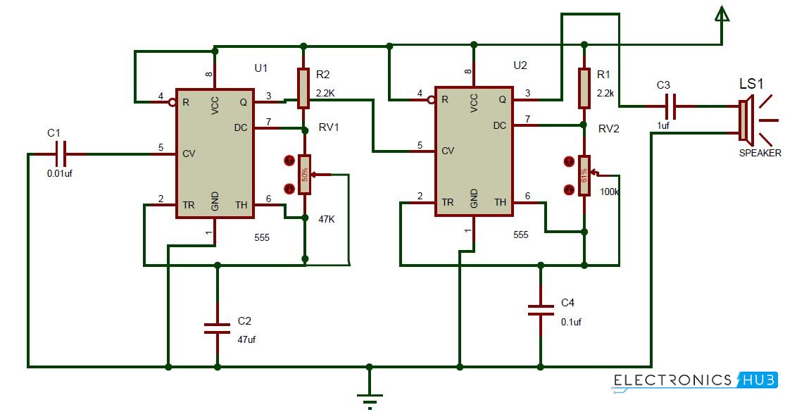
- Two 555 timer ICs – U1 and U2.
- Two Variable resistors – RV1 and RV2
- 4 Capacitors – C1, C2, C3 and C4.
- 2 Resistors – R1and R2
Ding Dong Bell Sound Generator Circuit Design:
The circuit consists of two 555 timer ICs arranged as shown in the circuit diagram. The first timer IC is connected in astable mode to produce pulse of frequency 1Hz. The 4th and 8th pins are shorted and connected to the resistor of 2.2K whose other end is connected to the pin of the timer IC. Sixth and seventh pins are connected to the variable resistor. Sixth and second pins are shorted and connected to the ground of 9v through a capacitor of 47uf. Fifth pin is connected to the ground through a capacitor of 0.01uf. First pin of the IC is connected to the ground.
Related Post: Automatic Doorbell Ringing Circuit with Object Detection.
The output pin of the first IC is connected to the control pin i.e. Fifth pin of the second IC. The second IC is also operated in astable mode again. 4th and 8th pins are shorted and connected to resistor of 2.2 k ohms whose other end is connected to the seventh pin of the IC. A variable resistor 100K is connected between sixth and seventh pins of the IC. Sixth pin and second pin are shorted and connected to the ground through a capacitor of 0.1uf. First pin is directly connected to the ground of 9v.Output pin of the IC is connected to the speaker through a capacitor of 1uf.
How Ding Dong Sound Generator Circuit works?
- Initially power the circuit.
- The “Ding Dong ” sound can be heard from the speaker.
- When the power is on the circuit is operated in the astable mode.
- As the voltage is applied to the timer, the capacitor starts charging through the resistors R1 and R2.
- When it reaches 2/3 of VCC, it is detected by the sixth pin and seventh pin is connected to the ground.
- Thus capacitor starts discharging, through the RV1 resistor.
- When voltage of 1/3 VCC is detected it again starts charging, thus this process continuously produces the pulse of frequency 1Hz.
- This is applied to the second timer through its control pin.
- Thus the frequency of the second timer is modulated and is applied to the speaker through a capacitor.
- The external RC circuit decides the time delay with which the waveform should be produced.
- Hence one can hear the “ding dong” sound produced.
Ding Dong Sound Generator Project Output Video:
Ding Dong Bell Sound Generator Circuit Applications:
- The circuit can be used as a door bell by connecting the supply to a switch.
- With some modifications it can be used to produce different sounds.
Ding Dong Bell Circuit Limitations:
- As the applied voltage is 9V, it cannot produce more sound.

One Response
The circuit diagram is missing a 3rd resistor between the 3rd and 5th pins connecting the left 555 IC Chip to the right 555 IC Chip. The video provided shows this. I used a 100k Ohm resistor and adding this resistor gives it that “ding dong” tone.
Hopefully I save someone the trouble.