Alarm Clocks are very useful devices in today’s busy life. They are designed to make a signal / alarm at a specific time. The use of digital alarm clocks has increased over years with development in electronics.
The advantage of digital alarm clocks over analogue alarm clocks is that they require less power, the time can be set or reset easily and displays the time in digits. Design of a simple digital alarm clock is explained here.
Using this digital alarm clock, time can be displayed in 24 HR format using an LED display and alarm can be set to a specific time. Alternatively, the digital alarm clock circuit can also be used to turn ON/OFF and electrical appliance after a specific time.
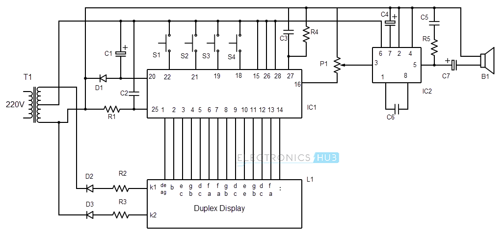
Digital Alarm Circuit Diagram
Digital Alarm Circuit Components
- IC1 – LM 8560
- IC2 – LM 386
- Duplex LED Display
- T1 – 0-12V / 500mA Transformer
- D1, D2, D3 – IN4001
- R1 – 100K
- R2, R3 – 120
- R4 – 91K
- R5 – 10
- P1 – 10K Potentiometer
- C1 – 470µF
- C2, C3 – 10nF
- C4 – 10µF
- C5, C6 – 100nF
- C7 – 100µF
- B1 – Buzzer
- S1, S2, S3, S4 – Switches
Digital Alarm Circuit Design
LM8560
The heart of the digital alarm clock is the IC LM8560. It is an alarm equipped digital clock IC. The drivers required to drive a duplex LED display to show the time are in-built to the IC. The functions of the IC LM8560 are display of current time, alarm support, snooze function and supports 12 HR and 24 HR time format.
LM386
It is a low voltage audio power amplifier. It is used in the circuit to drive the alarm buzzer. The alarm output of the LM8560 is given to power amplifier through a potentiometer.
Duplex LED Display
In the digital alarm clock, to display the information like current time, alarm notification etc. we use a duplex LED display. There is no need for any extra drivers to drive the display unit as all the required drivers are built in to the digital clock IC.
Push Button Switches (S1 – S4)
These four switches are used to set time, set alarm and turn off the alarm. When setting time and alarm in the digital alarm clock, both Hours and Minutes can be set separately using these switches.
Diodes (D1, D2, and D3)
Diode D1 in combination with the capacitor C1 will produce a DC voltage that is supplied to the IC1 (LM8560). Diodes D2 and D3 act as switch signal generator to the cathode of the duplex display. They work in relation to the input of the LM8560.
Buzzer (B1)
The main function of the digital alarm clock is to signal an alarm at specified time. A buzzer is used for this purpose which is driven by an audio power amplifier.
Transformer (T1)
A transformer is used to step down the 220-240 V AC supply to 12 V AC supply.
Digital Alarm Circuit Working
A digital alarm clock is a very useful device as it can display the current time as well as function as an alarming device. The circuit shown above can act as a simple digital alarm clock without requirement of any programming.
The components required and the complexity of the circuit are less. The working of the above shown digital alarm clock is as follows.
As explained in the component description, the heart of the digital alarm clock circuit is the digital clock IC LM8560. The input from the mains is given to the transformer which converts the input voltage to 12V AC.
A diode (D1) and a capacitor (C1) are used to convert this AC voltage to DC and supplied to the Vdd (Pin 20) of the IC1. IC1 (LM8560) works at a frequency of 50/60 Hz. This signal can be supplied from the mains supply using the resistor R1 to the Pin 25 of the IC1.
In relation to the input of the IC1, corresponding inputs to the cathode of the display are given through the diodes (D2 and D3). After switching on the power, we need to set the time. This is the current time to be displayed. In order to set the current time, we use the switches S1 and S2.
Switch S1 is used to set Hours and S2 is used to set Minutes. LM8560 automatically triggers the display connected to it and the time will be displayed on the duplex LED display.
The duplex display is a 4-bit seven segment LED display, where two bits are for displaying the Hours and two bits are for displaying Minutes and the Hour and Minute bits are separated by a colon.
Once the time is set, we can set the alarm using the switches S1, S2 and S3. In order to differentiate between the setting of current time and alarm time in the digital alarm clock, we use the switch S3 which internally triggers the alarm display of the LM8560.
In order to set the alarm, we need to hold the switch S3 and set the Hour and Minutes of the alarm time by using switches S1 and S2 respectively. Once the alarm is set successfully, the digital clock IC waits for the alarm time and once the alarm time is reached, an alarm output at the Pin 3 is generated.
This can be connected to a small buzzer directly for alarm output. But in order to get special alarm tones from the digital alarm clock, we can use special alarm signals. But to drive these special buzzers, we need an audio power amplifier. Hence, the IC LM386, which is a power audio amplifier, is used in the digital alarm clock circuit.
The alarm output of the IC1 (LM8560) is given to the input (Pin 3) of the IC2 (LM386) through a potentiometer P1. The potentiometer is used to control the volume and pressure of the alarm signal from the buzzer.
Once, the digital alarm clock starts the alarm signal, we need to stop this alarm. For this, we use the switch S4. The switch S4 can also be used to cancel the alarm any time before triggering.
This digital alarm clock can also be provided with snooze and repeat alarm facilities. Additional Pins of the IC1 (LM8560) have to be used in the digital alarm clock circuit in order to use these functionalities.
Guidelines & Alternative Components
- The digital alarm clock can be used to view the current time as well as act as an alarming device.
- Even though the supply given here is from mains, a battery powered device can also be designed. In order to design the digital alarm clock as a battery powered device, we need to use an oscillator to generate a 50Hz Sine wave for the digital clock IC (LM8560) to work.
- Some of the alternatives to the digital clock IC’s are TMS 3450, LM8361 and MM5387.
- The duplex display described in this digital alarm clock circuit is Longtek 6052X-S. Other alternatives can also be found.
- To use the snooze and repeat alarm functionalities of the digital alarm clock, we need to add two more switches to the digital clock IC (LM8560).
- The digital alarm clock circuit can also be used as a timer for electric appliances where they can be turned ON/OFF after a specific time. For this, we need to use an additional pin (Pin 23) on the digital clock IC (LM8560) with a switch. This pin has a sleep functionality.

4 Responses
please tell me where to get the duplex display? can i get it from ebay?
How many types of ic can used in this digital alarm clock
HOW TO HANDLE BIG 7 SEGMENT LED DISPLAY WITH THIS CIRCUIT ?
thank you soo much for this article! im a sophomore doing a physics project and thanks to you I could perfectly understand the circuit, and i never did this before!