Introduction
In this project, I will show How Speed Control of DC Motor can be implemented using 555 and Pulse Width Modulation (PWM).
We use DC Motors in many systems in our day to day life. For example, CPU fans, fume extinguishers, toy cars etc. are all DC Motors which are operated by DC power supply. Most of the times we will have to adjust the speed of the motors as per our requirement.
A CPU Fan for example, must be operated at high speed when the CPU is preforming heavy tasks like games or video editing. But for normal usage like editing documents, the speed of the fan can be reduced.
Although some systems have an automatic adjustment system for fan speed, not all systems possess this functionality. So, we will have to adjust the speed of the DC Motor ourselves occasionally.
How Speed Control of DC Motor is implemented?
There are multiple ways to adjust the speed of a DC Motor manually. The simplest way to achieve this is with the help of a variable resistor i.e. we can adjust the speed of a DC Motor by using a variable resistance in series with the motor.
But this method is usually not prepared for two reasons. The first reason is energy wastage i.e. the resistor dissipates the excess energy as heat. The second reason is if we want to use any devices like microcontrollers or any other digital equipment for automating our DC Motor speed control, then this method cannot be used.
A more efficient way to proceed is by using Pulse Width Modulation technique to Control the speed of our DC motor.
Also Read the Related Post – Stepper Motor Controller using AT89C51 Microcontroller
Circuit Diagram of PWM Based DC Motor Speed Control

Components Required
- 555 Timer IC
- 12V DC Motor
- 1N5819 x 2
- 1N4007
- 100nF
- 100pF
- 10KΩ Resistor
- 100KΩ Potentiometer
- IRF540 MOSFET
- Mini Breadboard
- 12V Power Supply
- Connecting Wires
Circuit Design
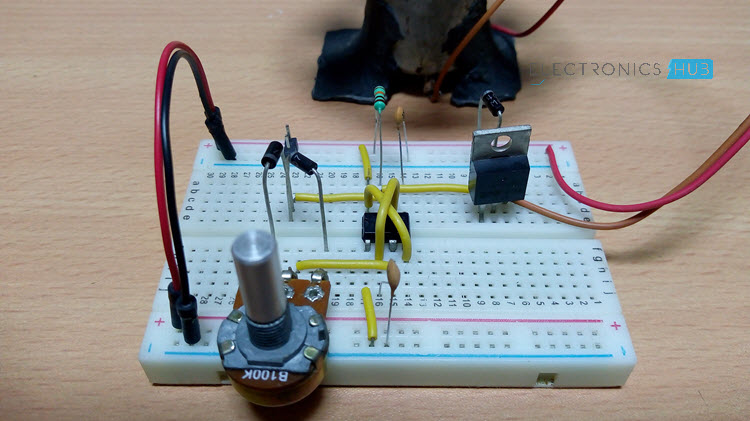
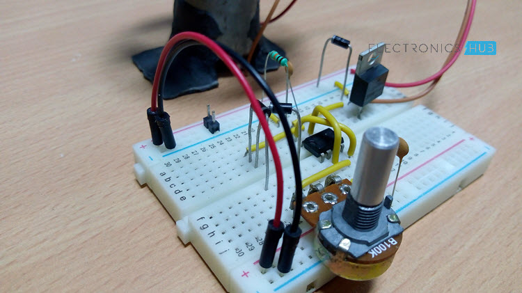
I am not going to explain the Pin Diagram of 555 IC and willassume that you are already familiar with that. Continuing to design of the circuit, Pin 1 of 555 is connected to GND. Pins 8 and 4 are connected to +12V Supply.
Pins 6 and 2 are short and a 100nF Capacitor is connected between Pin 2 and GND. The wiper pin of the POT is connected to Pin 3 of 555. Two Schottky diodes (1N5819) are connected to the other two pins of the POT as shown in the circuit diagram.
The common point of the diodes is connected to Pin 2. Pin 7 is pulled high with the help of a 10KΩ Resistor. The Gate terminal of the MOSFET is connected to Pin 7 of 555. The motor is connected between +12V Supply and Drain of MOSFET while the Source of MOSFET is connected to GND.
A PN Junction Diode is connected across the Motor terminals to prevent the back emf.
NOTE: I haven’t used the Schottky Diodes but replaced them with simple 1N4007 Diodes as the frequency of the PWM is less (around 220Hz).
How Speed Control of DC Motor Circuit Works?
In this circuit, the DC motor is operated by a 555 integrated circuit. The IC 555 in this circuit is being operated in astable mode, which produces a continuous HIGH and LOW pulses.
In this mode, the 555 IC can be used as a pulse width modulator with a few small adjustments to the circuit. The frequency of operation of the circuit is provided by the passive parameters of resistances and capacitors attached to it.
Read the following Post also: Water Level Alarm Using 555 Timer
NOTE:
- One of the best things about this circuit is that you can make it work as an astable multivibrator with little hardware and little cost, which can save both the cost involved in making it as well as the space on the printed circuit board (PCB).
- If you want a sophisticated pulse width modulator which works more accurately and which can have more adjusting capabilities, then it is better to use a microcontroller based pulse width modulator than the one which we are using now.
- However, the circuit or the application for which we are using a pulse width modulator is not so sensitive and hence does not demand so much of accuracy. In such a case, the circuit which we are using with a bare IC 555 is better as it saves our monetary as well as space resources in building the circuit.
- The duty cycle of the circuit can be changed by changing the value of the potentiometer. If we increase the duty cycle, the speed of the motor increases and if we decrease the duty cycle, the speed of the motor decreases.
Are you interested to do this project using microcontroller? Then go to the post – How PWM based DC Motor Speed Control Circuit Works using Microcontroller?

27 Responses
Nice…thanks for this.
Solar system the diagram please the send
Sir I am studying in class 11 science can you give me physics project according to my level but experimental part should between 10 and 15 pages
thank you very much.
I checked this same project at another site, but in that I found the values of some components are different.So I want to know whether it is fine or not to use different values of components of same project.
Backwards capacitors ! check your EL Caps symbol,
Thanks.
very simple and effective. I like it
Can we use transistor in the place of MOSFET??
No you cant….as it would burn off due to relatively high current demand than rated capacity of general bc547 transistors you are saying. Mosfets having higher current capacity are preferred above general transistors.
what kind of DC motor it is?
series, shunt or compound motor?
I am genuinely thankful to the holder of
this site who has shared this wonderful paragraph at here.
can i use 10k potentiometer instead of 100k
Please send all details about the project
Sorry, but I thing there is a mistake of connections in circuit diagram drawing pins 7 and 3, In effect this is because pin 7 must not be connected at gate of IRF540 transistor, but must be connected at sliding point of 100 K potentiometer. And pin 3 must not be connected at sliding contact of 100 K potentiometer: but must be at gate of IRF540, transistor, and this is because pin 3 is output of 555.. ¿isn`t?. Thanks.
Please send advantages ,disadvantages and applications of this project
Can any body tell me that what range of current is necessary for this circuit if i use 12v battery ., and if i use 6v battery
at 12v and 6v the circuit would work fine. The current handling capacity of the circuit for the motor depends upon which MOSFET you’re using.
MOSFET IRF540
Maximum Power Dissipation (Pd): 150 W
Maximum Drain-Source Voltage |Vds|: 100 V
Maximum Gate-Source Voltage |Vgs|: 20 V
Maximum Gate-Threshold Voltage |Vgs(th)|: 4 V
Maximum Drain Current |Id|: 30 A
I need to use this to reduce the speed of a 12v cooling fan on a vw microbus. The power consumption is 40A at 12v for normal speed but need to reduce the speed 30%. I assume the mosfet IRF 540 will have to be exchanged for something on a heatsink that can handle 200w.any help?
Try IRF1404,
Maximum Power Dissipation (Pd): 200 W
Maximum Drain-Source Voltage |Vds|: 40 V
Maximum Gate-Source Voltage |Vgs|: 20 V
ID @ 25°C – Continuous Drain Current, VGS @ 10V – 202 A
ID @ 100°C – Continuous Drain Current, VGS @ 10V – 143 A
Maximum Junction Temperature (Tj): 150 °C
My brother recommended I would possibly like this website. He was
once totally right. This put up actually made my day.
You cann’t imagine just how much time I had spent for
this information! Thanks!
I need working video and documentation of this project.
Sorry, at present we don’t have any working video of this project.
but, we have a similar project with working video – https://www.electronicshub.org/speed-controller-using-555/
the only difference here is we used IRFZ46N instead of IRF540.
Will this work with a 36 volt dc motor, for a scooter?
Definitely No.
it will fry the circuit.
But, simply to run the motor (NO LOAD) you use this circuit by starting the motor slowly (to avoid starting current) with a proper heat sink for MOSFET.
I like it very much!
Helped alot,, ” Thank you for all this”. 🙏🙏🙏