Inverter is a small circuit which will convert the direct current (DC) to alternating current (AC). The power of a battery is converted in to’ main voltages’ or AC power. This power can be used for electronic appliances like television, mobile phones, computer etc. the main function of the inverter is to convert DC to AC and step-up transformer is used to create main voltages from resulting AC.
Block Diagram of Inverter:
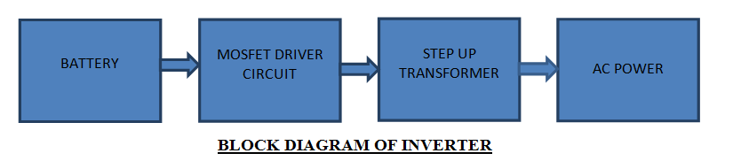
In the block diagram battery supply is given to the MOSFET driver where it will convert DC to AC and the resulting AC is given to the step up transformer from the step up transformer we will the get the original voltage.
100W Inverter Circuit Main Components:
CD4047: CD4047 is a multi vibrator with very low power consumption designed by TEXAS INSTRUMENTS.it can operate in monostable multivibrator and also astable multivibrator in the astable multivibrator mode it can operate in free running or gatable modes and also provides good astable frequency stability. It can generate 50% duty cycle which will create a pulse, which can be applied for inverter circuit. This is mainly used in frequency discriminators, timing circuits frequency divisions etc.
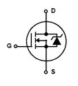
IRF540: IRF540 is a N-channel enhanced mode silicon gate field effect transistor (MOSFET).they are mainly used in switching regulators, switching converters relay drivers etc. the reason for using them in the INVERTER circuit is the because it is a high switching transistor , can work in very low gate drive power and have high input impedance.
IRF540 Symbol:
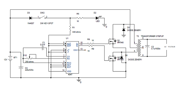
Simple 100W Inverter Circuit Diagram:
 Explanation:
- In the circuit diagram we can observe that 12V battery is connecter to the diode LED and also connected to the pin8 of the IC 4047 which is VCC or power supply pin and also to pin 4 and 5 which are astable and complement astable of the IC. Diode in the circuit will help not give any reverse current, LED will work as a indicator to the battery is working or not.
- IC CD4047 will work in the astable multivibrator mode. To work it in astable multivibrator mode we need an external capacitor which should be connected between the pin1 and pin3. Pin2 is connected by the resistor and a variable resistor to change the change the output frequency of the IC. Remaining pins are grounded .The pins 10 and 11 are connected to the gate of the mosfets IRF540. The pin 10 and 11 are Q and ~Q from these pins the output frequencies is generated with 50% duty cycle.
- The output frequency is connected to the mosfets through resistor which will help to prevent to the loading of the mosfets. The main AC current is generated by the two mosfets which will act as a two electronic switches. The battery current is made to flow upper half or positive half of the primary coil of transformer through Q1 this is done when the pin 10 becomes high and lower half or negative half is done by opposite current flow through the primary coil of transformer, this is done when pin 11 is high. By switching the two mosfets current is generated.
- This AC is given to the step up transformer of the secondary coil from this coil only we will get the increased AC voltage , this AC voltage is so high; from step up transformer we will get the max voltage. Zenor diode will help avoid the reverse current.
NOTE: The generated AC is not equal to the normal AC mains or house hold current. You cannot use this voltage for pure electric appliances like heater, electric cooker etc. Because of the fast switching of mosfets heat is dissipated which will effect the efficiency, use heat sink to remove this problem.
Related Posts:

26 Responses
nice!
Good blog for Electrical And Electronics Engineering Students.
how can i get a step up transformer in my city ,could u plz help in update the price.
where i get step up transformer in india,tamilnadu,madurai?
send me the answer quickly…
Bhai step up transformer shop se milta h.
This circuit is working properly,but i can’t get transformer…
pls type the rating of transformer…
use 12-0-12 5A transformer…..center tapped transformer
nice
Can you please tell me that how can we connect the capacitor directly with the battery??
Because as capacitor blocks DC. So the output current from the capacitor is zero.
The normal transformer present in the market is enough or we have to buy specific (step up or step down) transformer… please help me
when the +12 is connected to mid terminal of transformer at secondary winding, that time wire is heated and goes burn, what should i do, i am in very big confusion.
super circut for the electrical
so nice
transformer rating is very impotant in this circuit…..minimum 5A transformer should be used…..maximum as per ur required ur problem is heavy load in the transformer…..@nitesh
I need a video tutorial for this circuit.
Thanks
plz send video tutorial
Can we use this inverter for maximum 2 hours ?
we are like every circuit.
how much rupees invest for this project
what will be the overall cost of project
let me know why you use zinner diode on drain of MOSFET
Can i use a car battery???
Where the inverter use?
the inverter in showing output voltage but bulb is not working
I made it
Works perfectly only that my transformer heats up a bit
Good circuit
any 5 Amp. transformer can be used. Each Normal transformer is having 2 side i.e. primary and secondary primary is having 2 wires and secondary is having 3 wires like 12 volt 0 volt 12 volt or 6 volt 0 volt 6 volt. In general equipment we used step down transformer and direct AC voltage applied to its primary side i.e. 2 side wire and we get step down voltage from other side i.e. where 3 wires of available ( in some cases both side are two wires also ). If you give 12 volt to secondary winding side then you will get high voltage from other end ( i.e primary side ) Primary winding can be seen ( thick ( Big ) gauge copper wire ) and secondary winding is thin ( small ) gauge size . In any electronic spare part shop, this types of normal or special transformers are available.
hello brother can u provide me design calculation of this inverter circuit 100W. I need this calculating values step-by-step