In this tutorial, we will learn about Photovoltaic Cells, Solar Panels, Construction of Solar Cells, Photovoltaic Arays, the need for Bypass Diodes in Solar Panels, maximum power from solar panels etc.
Need for Bypass Diodes in Solar Panels
It is necessary to add the additional components to bypass or circumvent the shaded or damaged parts of PV (photovoltaic) cells, to continue the producing of power usually. These additional components which allow the flow of current through PV cells when the cells are not able to produce power can be termed as bypass diodes.
These diodes are necessary because a small damage or any disturbance in the PV module may affect the output current substantially. The effect in output current may be due to the cells in the module which are connected in series fashion, a single PV cell with some shade and due to the modules in a string can stop producing the power.
Bypass diodes are quite similar to the diodes that are used in the solar cells where the bypass diodes allow greater amount of current to pass through them with a very little amount of losses in them. In general, bypass diodes are arranged in reverse bias between the positive and negative output terminals of the solar cells and has no effect on its output.
Preferably there will be one bypass diode for each and every solar cell, but this is more expensive, so that there is one diode per small group of series connected solar cells. They are normally connected along with the several solar cells where no current is allowed to pass through them in the case when all the cells are in use without any shading.
The bypass diodes are helpful in the special cases when the cells are unable to pass the current through them. This type of bypass diode connection prevents the loss of power which allows the solar group to handle the real – world problems more efficiently.
Consider the above connection, if one of the connected panels is shaded for some reason. The panel will not produce any amount of significant power and the panel will also have a higher resistance which blocks the power flowing of the unshaded panel. Then the bypass diodes came into existence as shown in the diagram.
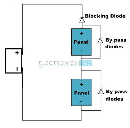
Consider if one of the panels is shaded in the above diagram, then the current of the unshaded panel flows through the bypass diode to avoid the higher resistance and current blocking of the shaded panel. Bypass diodes are useless, unless the panels are connected in a series fashion to produce high voltage.
Recently, some solar panels are being manufactured by the cells divided into groups with a built in bypass diode in that group. Solar modules with bypass diodes are manufactured because of two reasons. Primarily, the bypass diode improves the overall system performance of the solar module. The second reason is that they can provide a greater amount of product safety.
Under standard test conditions solar modules consistently can produce a maximum voltage of nearly 0.5 Vdc. The standard cell configuration of a solar module has 72 cells connected in a series fashion to produce an operating voltage somewhere nearly around 36 Vdc. Typically, a bypass diode is connected in parallel with every 24 cells in a 72 – cell solar module.
Effects of Partial Shading
A solar cell that is shaded will not able to pass current and/or voltage to an unshaded cell through them, which causes the maximum power rating of the shaded cell to drop as a result of shading. More the cell shading more will be the drop in power. A cell with 75% shading would be more worsen than the three cells with 25% shading.
The unshaded cells develop a negative voltage and draws power than the shaded cells since they try to pass more amount of current than the shaded cells. When the power output of the shaded string reduces, the power output of the remaining panels in the string reduces as well. The inverter circuit will try to reduce the power output, and also eventually the output voltage of the string also drops out of the operating window of the inverter.
In such a case, under shaded conditions, a string of cells that are connected in a series fashion may produce a voltage drop of 12 Vdc.
When a bypass diode is connected in parallel to the string of cells that are connected in series, produces a voltage drop of around 0.7 Vdc. As the electricity flows through the least resistance path, here the current flows through the diode and bypasses the shaded cells.
However, if the bypass diodes were not present in the circuit, the effect of the shading would be even greater as the shaded solar cells draw about 12 Vdc, so that the solar module’s voltage may be reduced to 24 Vdc.
Solar Panels Safety
The most horrible condition that can be imaginable with a solar module that has no bypass diodes is that it may cause fire and the by-product certainly will be the heat. This is improbable but possible under certain possible conditions. After a few days of operating under the shaded conditions, the additional amount of heat produced and multiple temperature cycles may cause the solar cell joints weak.
If the joints get more weaken and disconnect, there might be a possibility of producing an electrical arc. The high temperature penetrating from the electric arc may cause the glass to explode by allowing oxygen into the lamination of glass which holds the cells in the solar panel. In such a case the high and flammable EVA which holds the glass laminate and solar cell together may catch the fire.
This condition has to be avoided at all costs. Hence, bypass diodes are therefore needed in all solar electric modules/panels.
Photovoltaic Solar Cell Construction
A photovoltaic cell is created when a positively charged P – type semiconductor and a negatively charged N – type semiconductor placed in opposite directions to each other which forms a diode. In practice, this semiconductor sandwich is combined with supporting materials otherwise can be called as doping materials to make the diode.
This diode is connected in a circuit by means of metal conductors on both the top and bottom of the silicon sandwich to make panels, where they can be arranged in an arrayed fashion to provide different amounts of electricity.
Actually the PV cell includes an anti‐reflective coating to accept the most amount of sunlight into the silicon sandwich. This anti reflecting sheet tries to reduce the amount of sunlight reflecting from the glass by allowing the most amount of sunlight to hit the photovoltaic cell and increases the solar panel’s efficiency.
The photovoltaic cell is the vital element in a whole photovoltaic system, the photovoltaic panel is used to make a cell or a group of cells make usable. In photovoltaic panel, photovoltaics may be used alone or in a group of panels to power the large number of different electrical loads. Various types of photovoltaics vary in their size and structure.
- A single cell or multiple numbers of cells are the core part of the photovoltaic panel.
- A glass lamination is placed over the photovoltaic cell to protect it from the outside elements by allowing the sunlight to pass through to the photovoltaic cell.
- An additional plastic anti‐reflecting sheet is frequently used to improve the effect of the glass laminated cover and anti-reflective coating of the photovoltaic cell to block the reflection.
- A panel backing that is usually plastic and a frame will usually complete the photovoltaic panel by holding all the pieces together and thereby protecting it from damage during the process of installation.
Photovoltaic Array Connections
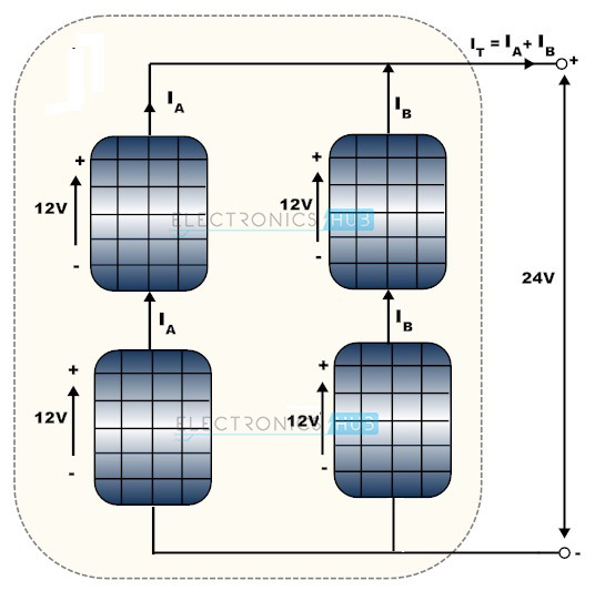
A simple photovoltaic array in the above diagram consists of four photovoltaic modules by producing two branches that are in parallel fashion where there will be two PV panels which are electrically connected together to produce a series fashioned circuit.
Therefore, the output voltage from the solar cell array may be equal to the sum of the voltages of PV panels that are in series connection. From the above circuit, the output voltage is Vout = 12V + 12V = 24 Volts. The output current of a photovoltaic array is equal to the overall sum of the parallel branch currents.
Photovoltaic Array Characteristics
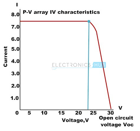
Short circuit current (Isc) and/or open circuit voltage (Voc)
The solar cells or photovoltaic panel can be typically characterized by the short circuit current represented as Isc and the open circuit voltage represented as Voc. The short circuit current of the solar panel can be termed as the current generated by the solar cell or panel if the output voltage is set to zero volts.
IL = ISC + ISC.(RS/RP) + IO.[exp[(q/kT).ISC.RS)-1]
ISC ~ IL
RS / RP and RS are negligible, the short circuit current of the solar cell or panel is close to the photocurrent IL that is generated by the cell and it is the maximum possible amount of current generated by the cell for a fixed amount of illumination.
IL = IO.{exp[(q/kT).VOC]-1}-(VOC/RP)
The open circuit voltage represented as Voc is the output voltage which is measured at zero solar current. The photocurrent is equal to the loss of current in the intrinsic element of the solar cell and open circuit voltage Voc is equal to the forward voltage of intrinsic diode Vd.
Maximum Output Power Point
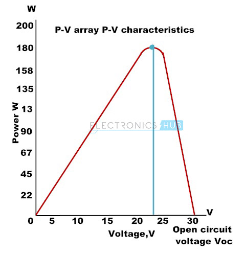
It is defined as the point at which the maximum amount of power is produced by the solar panel that is associated with the batteries and/or inverter load. The maximum output power point of the photovoltaic solar array panel can be usually measured in Peak Watts or Watts. It can be given as follows.
Pmax = (Imax) x (Vmax)
Voc and Isc Variations with Relevant Ambient Temperature
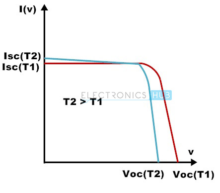
The open circuit voltage of the solar cell or panel can be linked with the forward voltage of the parasitic diode. Therefore, the open circuit voltage Voc is temperature dependent with negative temperature coefficient. The maximum value for open circuit voltage is the value at a minimum temperature at the junction that is specified in the panel data sheet.
The short circuit current of the cell or panel increases slightly with the junction temperature. The below figure shows the variations in the Voc and Isc with the temperature.
There will be a substantial bound to the amount of maximum current of a particular photovoltaic solar cell. The value of Imax of a PV solar cell or panel greatly depends on the size and structure of the cell/panel, the total quantity of sunlight directly hitting the panel/cell, its effectiveness in converting the direct sunlight power into the current and the semiconductor material type where the solar cell is fabricated from the semiconductor material either cadmium Telluride, cadmium sulphide, gallium arsenide and/or silicon and germanium etc.
Bypass Diodes in Solar Panels (Photovoltaic Arrays)
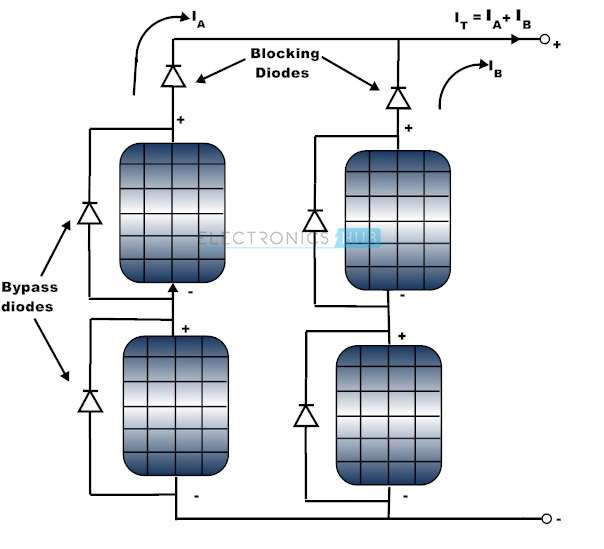
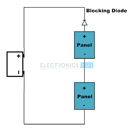
For example, assume that the output of solar panel is connected to a DC battery. So when there is light, solar panel produces the voltage and if this voltage is greater than the battery voltage battery charges. If no light incidents on the solar panel, then the battery discharges through the solar panel.
Hence, in order to avoid the battery discharge when the solar panel is in the dark we use a diode in series with the solar panel, this diode is called is blocking diode. In the above circuit the diodes which are in series with the solar panels are the blocking diodes.
In the above circuit the diodes which are connected in parallel with solar panels are called as bypass diodes. These diodes provide the separate path for the current to flow when the solar panels are shaded or damaged.
The blocking diodes and bypass diodes are physically same, but their functionality is different. Blocking diodes are also called as series diodes or isolation diodes. For each parallel brach of solar panels we will use a single blocking diode. Type and size of the blocking diode depend on photovoltaic array type.
Generally two types of diodes are used as a bypass diode in solar arrays. They are normal PN junction Si diode and Schottky diode. Both types of diode have wide range of current ratings. Schottky diode is preferable as a bypass diode than the normal PN silicon diode because it has less voltage drop of about 0.4V, where as normal Si diode has a voltage drop of 0.7V.
In recent days, most of the solar panel manufacturers include both blocking and bypass diodes in their solar panel design.
