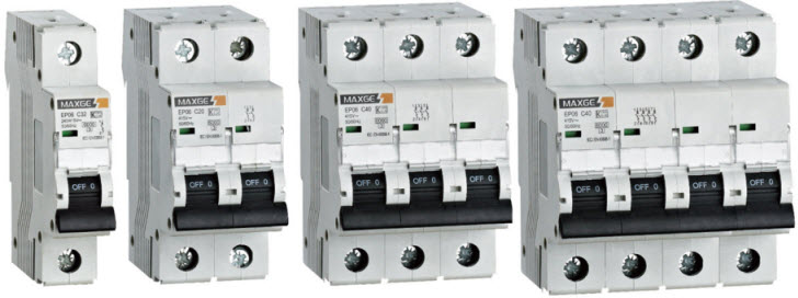
MCBs are popularly used for load break, protection and isolation of a sub-circuit including motor sub-circuits, lighting circuits and control circuits. The main usage area of MCBs is LV side, i.e., mainly in domestic, light-industrial or commercial applications.
These are manufactured in 1, 2, 3, and 4 pole versions of different current and voltage ratings. Similar to the HRC fuses, these are used for performing two major functions such as over current protection and short-circuit protection.
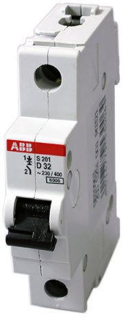
Miniature Circuit Breaker (MCB)
A miniature circuit breaker basically is an electromagnetic device that automatically operates (or breaks) the circuit, if the current in the circuit reaches to a predetermined value. It can replace conventional rewirable fuse in distribution board and are designed to operate accurately under both overloading and short circuit conditions.
MCBs can be reset quickly by an operator after its operation (tripping) thereby the circuit recloses, but in case of a rewirable fuse reclosing is not possible if a fault still exists. The tripping of MCB can easily be identified under overload or short circuit condition as its operating knob moves from ON to OFF position.
These are rated up to 100 Amperes, however, the trip current is normally not adjustable. It gives a better service for protection because it can operate 5 to 15 % excessive overloads.
Generally, MCBs are rated for 230 V AC for single phase, 415V AC for three-phase or 220V for DC supply. An MCB rated at 10 A current operating on thermal-magnetic trip is the most common type used in modern domestic consumer units and commercial electrical distribution boards.
The short circuit breaking capacity of MCBs ranges from 1 KA to 10 KA with 1-pole, 2-pole, 3-pole or 4-pole configurations. Two-pole MCBs have a combined handle for two poles that enables both legs of the MCB to trip if either side has an overload.
Three-pole MCBs are used for three phase supply and in such cases neutral is directly connected. Alternatively, we can use four-pole MCBs for three phases and a neutral connection.
The advantage of MCBs include, much faster operation than fuses, does not need any servicing or rewiring, easy to handle and more reliable. The operating time of the MCB is less than 1ms.
Generally, MCBs are designed to trip less than 2.5 milliseconds when a short circuit occurs or over current fault arises. In case of overheating or overload condition, MCB may take 2 seconds to 2 minutes for tripping based on the level of the overload.
“
»
Construction of MCB
Most MCB designs are of single pole construction for use in single-phase circuits. The complete system is housed within a plastic moulding and it is made of flame-retardant high strength plastic.
It results high melting point, high dielectric strength, low water absorption at saturation, low coefficient of linear thermal expansion, and high deflection temperature under load.
MCBs are fitted with arc chute stack consisting of various arc chutes (metal plates) which are held by the position by an insulating material. It is not necessary that arc chute stack always surround the contacts, and hence in some design arc runners are provided to move the arc into the arc chutes.
 Internal diagram of MCB
The thermal tripping mechanism consists of a thermal-magnetic arrangement where thermal action is provided by a bimetallic strip and in some cases by a heater. The tripping mechanism is activated by the deflection of the bimetallic strip. So the characteristics of bimetallic strip provide the particular delays under overload or fault currents.
A low resistance bimetal is used for high current MCBs and a higher resistance bimetal is used for low current MCBs. A heater may be incorporated around the bimetal to generate the sufficient heat for very low current MCBs.
The magnetic tripping mechanism consists of a coil which is wounded around a tube.
This tube has a spring-loaded slug and the slug movement operate the tripping mechanism. The magnetic field generated by the coil during the high fault current overcomes the spring force holding the slug in position. So the movement of slug actuates the tripping mechanism.
The coil is made up of thin wire with many turns for low rating MCBs and a thicker wire with fewer turns for higher heating MCBs. Depending on the required characteristics, the magnetic tripping is set by the manufacturer.
Working of MCB
The operation of the MCB includes two stages, i.e., thermal operation and short circuit operation. The former operation based on the thermal effect of over current while the later operation is based on the electromagnetic effect of over current.
All MCBs operate on the air-break principle where the arc between the contacts is forced into the splitter plates through arc runners. This causes to spilt single arc into a series of arcs and then extinguishes the arc by extracting the energy from the arc and by cooling it.
With the use of bimetallic strip, thermal operation is achieved in case overload conditions. When overload current flows through the MCB, the bimetallic strip gets heated and causes to deflect. In doing so, it moves the trip lever and releases the latch mechanism and hence the contacts open under spring mechanism.
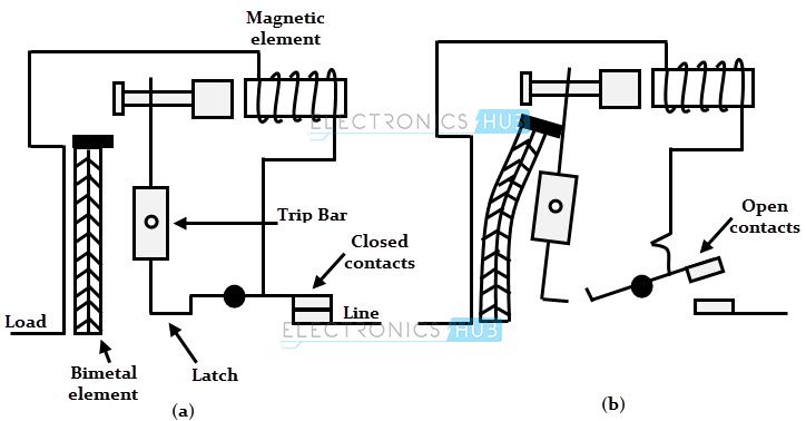
During the short circuit conditions, the large fault current energizes the solenoid and the magnetic field of the solenoid attracts the plunger which in turn strikes the trip lever and hence the immediate release of the latch mechanism.
The arc is produced during the separation of the contacts at overload as well as short circuit conditions. This arc is moved into the arc-cute stack under the influence of a magnetic field. So the arc broken down into partial arcs in arc chutes and they no longer exist due to the voltage drop of the arcs.
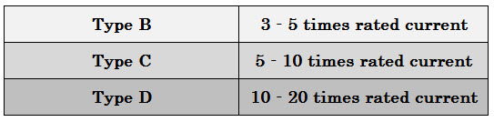
Types of MCBs
There are three standard characteristics are available for domestic as well as commercial MCBs and are given by B, C and D. Each type has its own function.
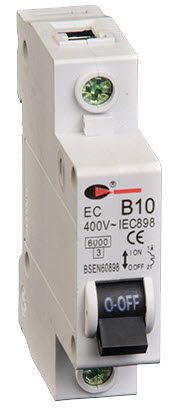
Type B MCBs are mainly used where switching surges are small or non-exist and are generally suitable for domestic applications and light commercial applications. There are no devices with long high starting current in domestic applications and hence the best suited MCB is type B.
These are designed to trip at fault currents in the range of 3 to 5 times the rated current. Suppose if the rated current is 10 A, then the MCB trips at 30-50 A.
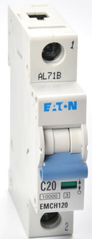
Type C MCBs are designed for high inductive circuits where surge currents are expected. These are generally used for commercial and industrial applications where a number of fluorescent lamps being turned ON or starting of small motors may give high surge currents.
These are less sensitive than type B MCBs and causes reduced nuisance trips. Type C MCBs are designed to operate or trip at the fault currents of 5-10 times that of rated current. For 10 A type C MCB, the operating current range is 50-100 A.
Type D MCBs are designed for heavy industrial applications where normal surge currents are very high. These are ideal for electric welders and site transformers where frequent high surge currents are expected.
The most common applications of type D MCBs include motors, UPS systems, X-ray machines, transformers and battery charging systems. These are designed to trip at 10-20 times the rated current. For 10 A type D MCB, the operating current range is 100-200 A.
The settings or characteristics of a MCB are fixed in the factory itself by manufacture and they are not adjustable at the user end or at the site. Tripping currents for operation at 0.1 Sec or less of different MCBs are given below.

One Response
gd