Star Delta Starter (Y – Δ) is a common type of three phase (3 phase) induction motor starters generally used in low starting torque motors.
Motor Starters are types switches (either electromechanical or solid state) that are designed to start and stop the motors by providing the necessary power to the motor and preventing the motor to draw excess current.
Star Delta Starter for 3-Phase Motor
A Star Delta Motor Starter is a type of Reduced Voltage Starter and it is also the most commonly used one. Before discussing the Star Delta Starter in detail, we will see why we need a motor starter in the first place and the different types of motor starters that are available.
Also read about: Direct Online or DOL Motor Starter
Why we need Motor Starters?
Generally, a motor, whether industrial or consumer, must be started with either no load or full load, based on the application it is used for. If the motor must be started with no load, it requires a small torque to get past the initial inertia.
But if the motor must be started with full load (or any load for that matter), the starting torque must be sufficient enough to start the motor with load and its inertia.
Generally, three – phase motors can be started by directly connecting the supply from the mains. In this case, the starting current is high and as a result, the starting torque of the motor is high. This torque will accelerate the motor to achieve its final speed.
Since the acceleration of the motor is high (fast), the copper losses i.e. loss due to heat, which is calculated using I2 x R, is considerably low.
This type of motor starting is applicable for small motor i.e. motors that are rated up to 5HP. But the same starting technique can’t be applied for higher capacity motors. The reason is explained below.
In large motors, the starting current is very high and if it is connected directly to the mains supply, there will be a huge voltage drop in the line. This voltage drop effects the behaviour of other systems and loads connected to the supply.
The starting current of large three phase induction motors can be as high as 6 times that of the maximum current (full load current).
Consider the following example for the purpose of explanation. A 415 V, 50 HP industrial motor is rated for a maximum current (full load current) of 70 A.
If this motor is started by directly connecting it to the mains supply, the starting current will be around 6 x 70 = 420 A. This is a very high current draw from the network and will definitely show an impact on other devices.
Hence, we need to start a three phase induction motor using an appropriate motor starter. Since torque of the motor is directly proportional to the square of the voltage (T ∝ V2), a reduction in voltage will result in a lower starting torque. This types of motor starters are called Reduced Voltage Starters.
There are many types of Reduced Voltage Starters. Some of them are listed below.
- Star Delta (Y – Δ) Starter
- Resistance Reduced Voltage Starter
- Auto Transformer Reduced Voltage Starter
- Increment Resistance Starter
- Part Winding Reduced Voltage Starter
- Reactance Reduced Voltage Starter
Star Delta Starter (Y – Δ Starter)
Star Delta Starter, which is sometimes called as Y – Δ or Wye – Δ Starter, is a common type of Reduced Voltage Starter. Star Delta Starter can reduce the starting current without the need of any external devices.
Generally, we use Star Delta Starters for three phase squirrel cage induction motors that are normally designed to work on a Delta Connection. The major applications of motors with Star Delta Starters are fans, pumps, centrifugal chillers in ACs, etc.
In a Star Delta Starter, the initial connection of the stator windings is in the form of Star. If VL is the Line Voltage and VP is the Phase Voltage, then the voltage at each stator phase is given by
VP = VL / √3
As the motor accelerates and gains speed, the stator windings are disconnected from the Star configuration and connected in the form of Delta. The following image shows the Star and Delta connections and their respective currents.
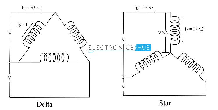
In the second image (image on the right), the windings of the stator are connected in Delta. We know that the Line Voltage and Phase Voltage are equal in Delta Connection and let the voltage across the stator windings be V. If I is the Phase Current through the stator winding in Delta connection, then line current is IL = √3 x I.
This is from the fact that the line current in a Delta Connection is root three times the phase current.
Coming to the first image (image on the left), the stator windings are connected in Star Connection. As V is the Line Voltage, the voltage across the windings in Star connection is given by V / √3.
As the voltage across the winding is reduced by 1 / √3 times, the current flowing in each winding is also reduced by the same amount. Hence, the phase current or the current through winding becomes IP = I / √3. Since the Line current and phase current in star connection are equal, the Line current IL = I / √3.
We can conclude from the above analysis that,
IL (in Delta) = √3 x I
IL (in Star) = I / √3
From the above two equations, we can conclude that the Line Current in Star Connection is 1/3 times that of the Line Current in Delta Connection.
Also, the starting torque of a motor is directly proportional to the square of the voltage at the windings i.e.
T ∝ V2
As we have established that voltage across the motor windings in star connection is 1 / √3 times the voltage across the motor windings connected in delta connection. Hence, the starting torque of the motor in star connection will be 1 / 3 times that of the torque when the motor is connected in delta connection.
Motor Windings in Star Delta Starter
Let us see the motor winding connections in a Star Delta Starter. Let the three stator windings of the three phase induction motor be called as X1 – X2, Y1 – Y2 and Z1 – Z2 where X1, Y1 and Z1 are the starting ends and X2, Y2 and Z2 are the closing ends (or finishing ends). The following image shows the motor windings connected in star and delta connections.
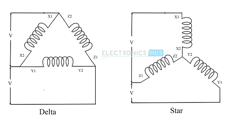
In a star connection, the finishing ends of the windings are joined together to form a neutral point. We can also connect all the starting ends of the winding to make the neutral point. In the above image, the finishing ends i.e. X2, Y2 and Z2 are connected together.
In a delta connection, the starting ends of one winding is connected to the finishing end of the other winding to form a structure as shown in the above image. The supply is given at the junctions. In the connection show above, the junctions are as follows: X1-Z2, X2-Y1 and Y2-Z1.
In a Star Delta Starter, the windings of the motor are first connected in Star Connection and with the help of switches, timers and contactors, the windings are connected in Delta Connection during normal running of the motor.
Types of Star Delta Starters
Based on the switching action between the Star Connection and Delta Connection, the Star Delta Starters are basically classified in to Manual Starters and Automatic Starters. We will see some of the common types of Star Delta Starters here.
Simple Manual Star Delta Starter
The following image shows the connection diagram of a simple manual Star Delta Starter.
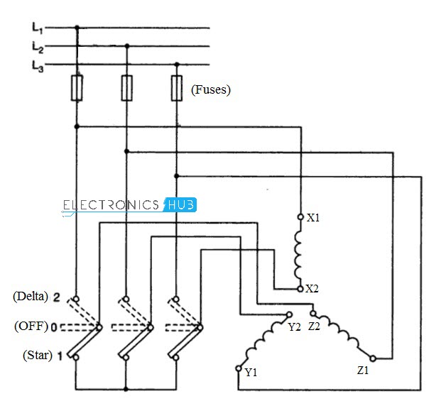
The switch in this starter has three positions: 0 (for OFF), 1 (for Star) and 2 (for Delta). If the switch is placed in 0 – position, the windings of the motor are open and the motor is OFF. To activate the Star Connection, the switch is moved to 1 – position.
During this position of the switch, the finishing ends of the windings i.e. X2, Y2 and Z2 are shorted. This completes the star connection and the motor starts rotating.
As the motor accelerates, it gains speed and as the speed of the motor approaches its rated speed, the switch is moved from 1 – position to 2 – position.
The 2 – position of the switch activates the Delta Connection as it establishes X2-Y1, Y2-Z1 and Z2-X1 contacts. The motor now runs in Delta Connection and reaches its rated speed without any problem.
Manual Star Delta Starter with Push Button
The following image shows the wiring diagram of a Push Button Operated Manual Star Delta Starter. This type of starter typically consists of 2 push buttons, 4 – pole 3 – position switch, a contactor and an overload relay.
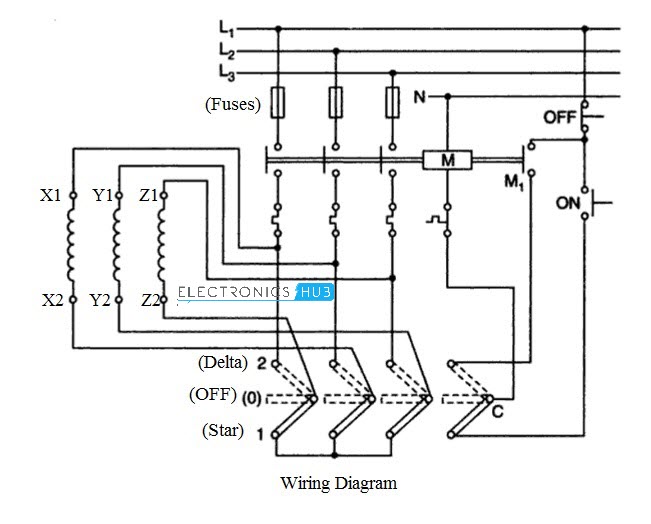 In the 4 – pole 3 – position switch, 3 poles are used for connecting the 3 windings of the motor to the supply with the 3 positions being 0 (OFF), 1 (Star) and 2 (Delta). The 4th pole in the switch is used in the control circuit.
When the switch is in 0 – position (OFF), if the ON Button is pressed, the contactor M doesn’t get energised. If the switch is moved to 2 – position (Delta or Run) and if the ON Button is pushed, even now the contactor M doesn’t get energised. In both these cases the motor doesn’t start.
Now, the position of the switch is moved to 1 – position (Star). If the ON button is pressed now, the contactor coil M gets energised and closes the contacts of the motor with supply. The Motor is now connected in Star Connection and as a result it starts rotating.
The ON Button must be pressed as the motor gains speed and the switch is moved to 2 – position (Delta). As the motor is running in Delta Connection, the ON button can be released as M1 will ]keep the contactor M energised.
The ON button can be released only after the motor windings are switched to Delta Connection. To turn OFF the motor, OFF Button can be pressed.
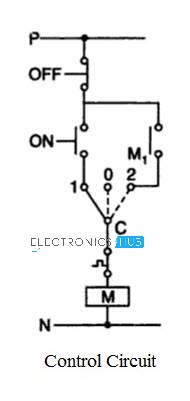
The following image shows the control circuit of the Push Button operated Star Delta Starter. This includes the Control Switch C, contact M1 and ON and OFF Push Buttons.
Semi – Automatic Star Delta Starter
In a Semi – Automatic Star Delta Starter, we require three contactors for connecting the motor windings is Star and Delta Connections. The wiring diagram of the Semi – Automatic Star Delta starter is shown in the following image along with the winding diagram of Delta Connection.
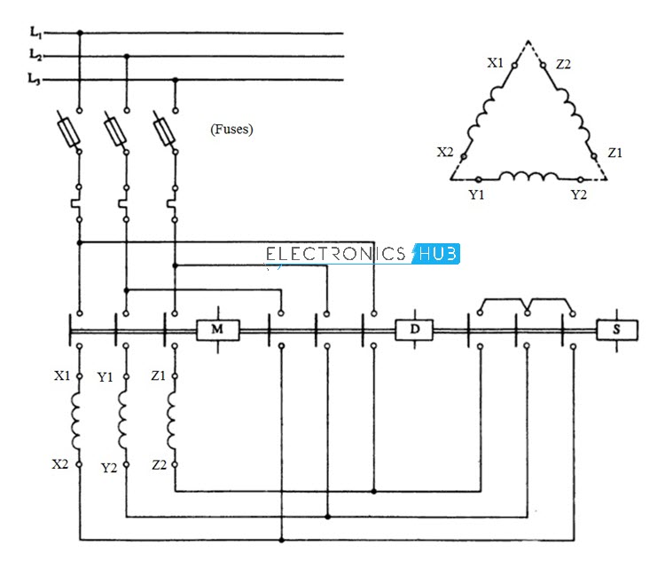
First, the contactor S (for Star Connection) will be used to connect the windings in Star Connection. Now, by closing the main contactor M, we can start the motor in star connection as X2, Y2 and Z2 are shorted.
After the motor gains speed, the contactor S is opened and contactor D (for Delta Connection) is closed so that the windings are configured in Delta Connection as the motor windings X2, Y2 and Z2 are connected to Y1, Z1 and X1 respectively.
It is important open the Star Connection (contactor S) before engaging the Delta Connection if not, short circuit takes place. The following image shows the control circuit of the Semi – Automatic Star Delta Starter.
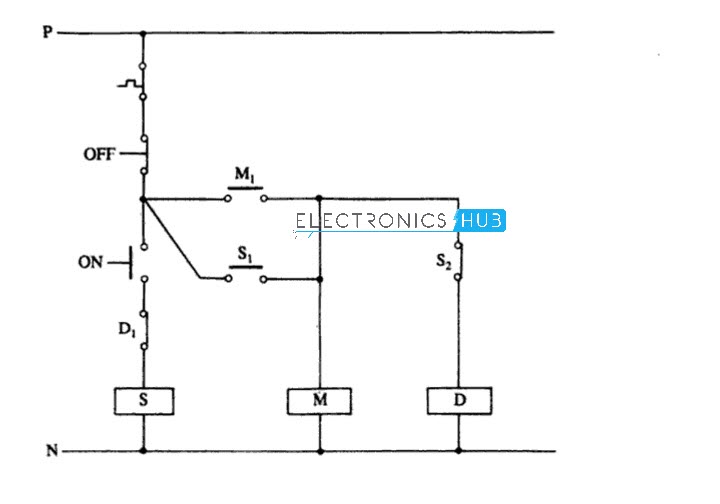
First, when we push the ON button, the contactor S is energized and as a result the motor windings are connected in star connection. The supplementary contacts of S i.e. S1 and S2 gets closed and opened respectively.
Since S1 is closed, the main contactor M gets energized and the motor starts in star connection. After this, the contactor M stays energized by the supplementary contact M1.
Since S2 is open, the Delta Connection cannot be started when Star Connection is activated and in order to activate the Delta Connection, we must disengage the Star Connection.
When the ON button is released, the contact S1 is open and S2 is close as the contactor S is de – energized. As S2 is closed and M is already energized by M1, the motor now runs in Delta Connection.
To turn off the motor, the OFF button is pushed, which will de – energize the contactors M and D (main and delta).
Read this interesting article Comparison between Star and Delta Connections
Automatic Star Delta Starter (Open Circuit Transition)
The main difference between manual star delta starters and automatic star delta starters is the automatic switching from Star Connection to Delta Connection based on predefined time intervals.
A Time Delay Relay is used to obtain the necessary time before switching from Star to Delta. Depending on the capacity of the motor and its load conditions, the time delay can be more or less around 10 seconds.
The wiring diagram of an Automatic Star Delta Starter is same as that of the Semi – Automatic Star Delta Starter. But there is a significant difference in the control circuit, which is shown in the following image.
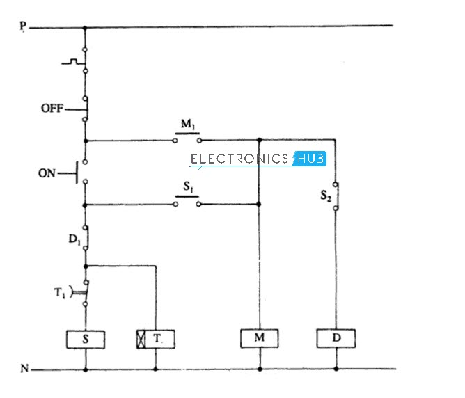
First, the ON button is pushed and the contactor S gets energized. This will close the contact S1 and hence the contactor M will get energized. Since both the contactors S and M are active, the motor starts rotating in Star Connection.
When the contactor S is activated, the Time Delay Relay T is also energized. As a result, the motor windings stay in Star Connection until the time set in the Time Delay Relay.
After the preset time (say 10 seconds) is up, the contact of Time Delay Relay i.e. T1 gets opened, resulting in de – energizing of contactor S.
As S is de – energized, S1 is opened and S2 is closed. Since contactor M is already activated by M1, and now that S2 is closed, the windings of the motor get connected in Delta Connection.
The contact D1, which is a supplementary contact of contactor D, is opened when the Delta Connection is active. This will avoid activating Star Connection when Delta Connection is active.
In this Automatic Star Delta Starter, the Delta Connection is established only after the Star Connection is released. This type of connection is called Open Circuit Transition.
Automatic Star Delta Starter (Closed Circuit Transition)
The Open Circuit Transition type Automatic Star Delta Starter discussed in the above section is sufficient for almost all motors but we need a Closed Circuit Transition type Automatic Star Delta Starter in order to block power disturbances.
A Closed Circuit Transition type Automatic Star Delta Starter can be designed by slightly modifying the Open Circuit Transition starting circuit.
The additional components are a 3 pole contactor and few resistors. The following image shows the wiring diagram of the Automatic Star Delta Starter with Closed Circuit Transition.
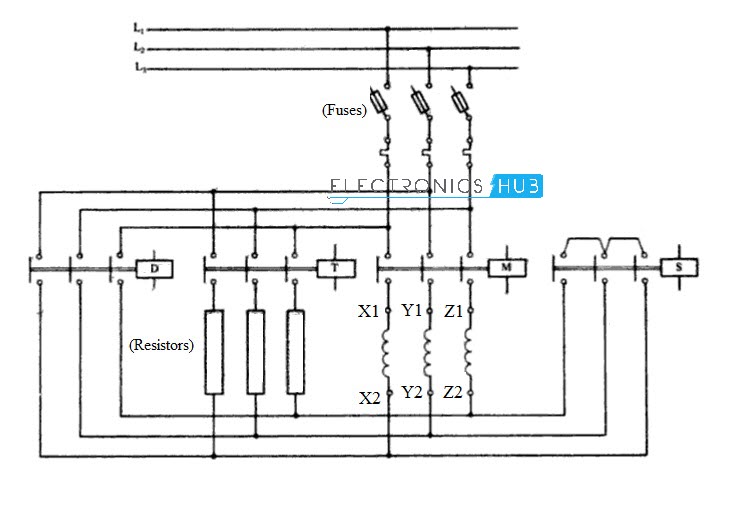
The main problem with Open Circuit Transition is that the windings of the motor gets disconnected from the supply for a small duration during the transition from Star to Delta Connection.
We can overcome this in Closed Circuit Transition by keeping the motor windings energized with the help of resistors when windings change from Star to Delta Connection.
During the startup, the contactors S and M (Star Connection Contactor and Main Contactor) gets activated and the motor starts rotating. As it gains speed, the Time Delay Relay Contactor T is energized.
The main difference between the open and closed circuit transitions is that the Timer Contactor T is connected in parallel to the Delta Contactor D through the resistors.
After the time delay, the contactor S is deactivated and the contactor D gets activated. As a result, the windings get connected in Delta Connection.
During this transition (opening of contactor S and closing of contactor D), the windings of the motor stay connected to the motor with the help of series resistors through contactor T.
The following images shows the control circuit for Closed Circuit Transition type Automatic Star Delta Starter.

When the ON button is pushed, the control relay contactor CR is energized and the corresponding supplementary contacts CR1 and CR2 will be closed. As CR2 is closed, the Star Connection contactor S is energized.
The auxiliary contacts of S i.e. S1 and S2 will be closed and opened respectively. Because of the contact S1, the main contactor M gets activated and thus the motor starts running in Star Connection. M stays energized with the help of M1.
Along with the main contactor M, the Timer A gets activated. After a predefined time, the auxiliary contact of A i.e. A1 is closed, which will energize the Timer Contactor T and Timer B.
Now, the energizing of the Timer T will result in connecting the resistors in parallel to the motor windings. The Timer B, which was energized by A1, operates after a time delay and opens its auxiliary contact B1.
Now, the open B1 will deactivate the S contactor, which will disengage the Star Connection at the motor windings. As S is de – energized, the contact S2 is closed and as a result, the Delta contactor is activated. The contactor T will help the Delta connected windings to stay connected to the supply through the series resistors.
As the contactor D is activated, its supplementary contacts D1 and D2 will be opened. Here, D1 will prevent the Star Connection to be activated while the Delta Connection is active and D2 will deactivate the contactors of Timer T, Timer A and Timer B. The motor keeps running in Delta Connection with the help of contactors D and M.

11 Responses
I have learnt alot today about star delta ,thank you alot keep on doing the great work you are doing
Thank you.
exelente informacion
good work, keep it up
i need to know when i connect motor with power from a star delta starter the motor starts but with a sound that is not normal and when i put delta it breaks from the mcb
i have learnt alot on star delta starters.. God bless for good work.
I follow the procedure but when I switched on power it directly energized delta contactor without pressing start button. what’s the problem?
Check the Delay Timer for Delta winding
I follow the procedure but when I switched on power it directly energized delta contactor without pressing start button then it harm alot. what’s the problem?
Nice explaination helped a lot …..
EXCELLENT INFORMATION AND PRSENTATION