Single phase induction motors are used in a wide range of applications where only single phase supply is available.
These are manufactured in fractional kilowatt range to meet the requirements of various applications such as ceiling fans, food mixers, refrigerators, vacuum cleaners, portable drills, hair driers, etc.
Let us discuss various types of single phase induction motors in brief.
What Are Single Phase Induction Motors?
As the name suggests, these motors operate on single phase AC supply. Single phase induction motors are extensively used in low power applications such as domestic appliances as mentioned above.
These are small in size and less expensive to manufacture. These motors are also called as fractional KW motors, because most of these motors are constructed in fractional kilo-watt capacity.
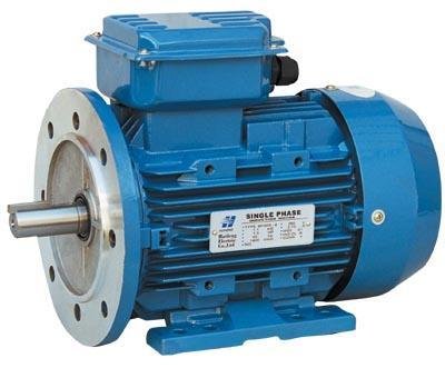
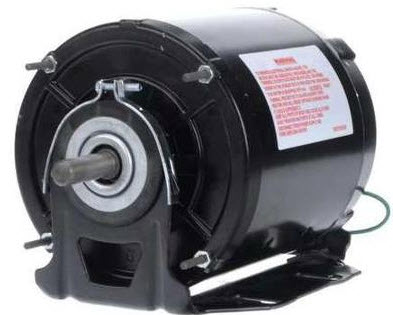
Single phase induction motors consist of two main parts; stator and rotor. The construction of these motors is more or less similar to a three-phase squirrel-cage induction motor.
The stator is a stationary part and it has laminated construction, which is made up of stampings. These stampings consists of slots on its periphery to carry the stator winding. This winding is excited with a single phase AC supply.
The rotor is a rotating part and its construction is of squirrel cage type. The rotor consists of uninsulated aluminum or copper bars which are placed in the slots.
These rotor bars are permanently shorted at both ends with the help of end rings as shown in figure.
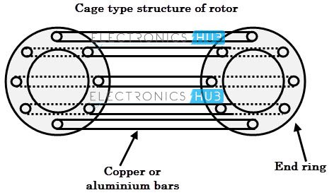
There is no physical connection between the stator and rotor, but there is a small and uniform gap between them.
The rotor acts as a conductor which when placed in the stator magnetic field, an emf is induced in it, produces its own magnetic field which further interacts with stator field to produce the torque.
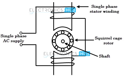 Whenever a single phase AC supply is given to the stator winding, an alternating magnetic field is produced around the stator.
Due to the pulsating nature of the field which reverses for every half-cycle, cannot produce rotation in a stationary squirrel cage rotor.
In case of three phase induction motor, the field produced by the supply is of rotating type and hence they are self starting motors.
But in case of single phase motors, the field produced by the stator is not rotating (but alternating only) and hence single phase motors are not self starting.
But, if the rotor is rotated by any other means (by hand or any tool), the induced currents in the rotor will assist with stator currents to produce revolving field. This field causes the motor to run in the direction it is started even with a single winding.
However, it is not possible to give initial rotation every time externally if the motors are attached to loads. This problem can be avoided by converting single phase motor into a two-phase motor temporarily in order produce revolving flux. This is achieved by providing a starting winding in addition to main or running winding.
The auxiliary or starting winding is made highly resistive whereas the main or running winding is made highly inductive.
Due to the large phase difference between these two, the torque produced by the rotor is high enough to start it. Once the motor reaches 75 percent of its speed, the auxiliary winding may be disconnected by a centrifugal switch and the motor able to run on a single main winding.
Single phase induction motors are used primarily for domestic and light-industrial applications where three-phase supply is generally not available.
Types of Single Phase Induction Motors
As mentioned above that, due to the rotating magnetic field of the stator, the induction motor becomes self starting. There are many methods of making a single phase induction motor as self starting one.
Based on the starting method, single phase induction motors are basically classified into the following types.
- Split-phase motor
- Capacitor start motor
- Permanent capacitor run motor
- Capacitor start capacitor run motor
- Shaded pole motor
 The rotating magnetic field is produced when there are minimum two alternating fluxes, having a phase difference between them.
The resultant of these two fluxes produces a rotating flux which rotates in space in one particular direction. So in all the above methods or say types of induction motors, the additional flux other than main flux should have a certain phase difference with respect to main or stator flux.
If the phase difference is more, starting torque will be more. So the starting torque of the motor depends on the rotating magnetic field and thereby, additional means (whether it is an auxiliary winding or anything).
Once the motor picks up the speed, this additional winding is removed from the supply. This is the basic principle followed by all these types of single phase induction motors.
Let us discuss these types of motors in brief.
Split Phase Induction Motor
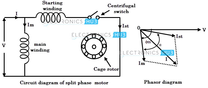
This is one of the most widely used types of single phase induction motors. The essential parts of the split phase motor include main winding, auxiliary winding and a centrifugal switch.
This is the simplest arrangement to set up a rotating magnetic field by providing two winding on the same stator core as shown in figure.
The auxiliary or starting winding carries a series resistance such that its impedance becomes highly resistive in nature.
It is not wound identical to the main winding but contains fewer turns of much smaller diameter as compared to main winding.
This will reduce the amount of start current lags the voltage. The main winding is inductive in nature in such that current lags the voltage by some angle. This winding is designed for the operation of 75 % of synchronous speed and above.
These two windings are connected in parallel across the supply. Due to the inductive nature, current through main winding lags the supply voltage by a large angle while the current through starting winding is almost in phase with voltage due to resistive nature.
Hence there exists a phase difference between these currents and thereby phase difference between the fluxes produced by these currents. The resultant of these two fluxes produce rotating magnetic field and hence the starting torque.
The centrifugal switch is connected in series with the starting winding. When the motor reaches 75 to 80 percent of synchronous speed, the centrifugal switch is opened mechanically and thereby auxiliary winding is out of the circuit. Therefore, the motor runs only with main winding.
Split phase motors give poor starting torque due to small phase difference between main and auxiliary currents. Also, the power factor of these motors is poor. These are mainly used for easily started loads such as blowers, fans, washing machines, grinders, etc.
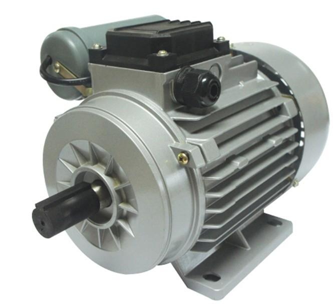
Capacitor Start Induction Motor
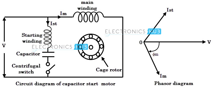
This motor is similar to the split phase motor, but in addition a capacitor is connected in series to auxiliary winding. This is a modified version of split phase motor.
Since the capacitor draws a leading current, the use of a capacitor increases the phase angle between the two currents (main and auxiliary) and hence the starting torque. This is the main reason for using a capacitor in single phase induction motors.
 Here the capacitor is of dry-type electrolytic one which is designed only for alternating current use. Due to the inexpensive type of capacitors, these motors become more popular in wide applications.
These capacitors are designed for definite duty cycle, but not for continuous use. The schematic diagram of capacitor start motor is shown in figure below.
The operation of this motor is similar to the split phase motor where the starting torque is provided by additional winding.
Once the speed is picked up, the additional winding along with capacitor is removed from the circuit with the help of centrifugal switch. But, the difference is that the torque produced by this motor is higher than split phase motor due to the use of capacitor.
Due to the presence of a capacitor, the current through auxiliary winding will leads the applied voltage by some angle which is more than that of split case type.
Thus, the phase difference between main and auxiliary currents is increased and thereby starting torque.
The performance of this motor is identical to the split phase motor when it runs near full load RPM. Due to the capacitor, the inrush currents are reduced in this motor.
These motors have very high starting torque up to 300% full load torque. However the power factor is low at rated load and rated speed.
Owing to the high starting torque, these motors are used in domestic as well as industrial applications such as water pumps, grinders, lathe machines, compressors, drilling machines, etc.
Permanent Capacitor Induction Motor
This motor is also called as a capacitor run motor in which a low capacitor is connected in series with the starting winding and is not removed from the circuit even in running condition. Due to this arrangement, centrifugal switch is not required.
 Here the capacitor is capable of running continuously. The low value capacitor produces more leading phase shift bur less total starting current as shown in phasor diagram.
Hence, the starting torque produced by these motors will be considerably lower than that of capacitor start motor. The schematic circuit of this motor is shown in figure below.
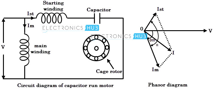
In this, the auxiliary winding and capacitor remains in circuit permanently and produce an approximate two phase operation at rated load point. This is the key strength of these motors.
This will result better power factor and efficiency. However, the starting torque is much lower in these motors, typically about 80 percent of full load torque.
Due to the continuous duty of auxiliary winding and capacitor, the rating of these components should withstand running conditions and hence permanent capacitor motor is more than equivalent split phase or capacitor start motors. These motors are used in exhaust and intake fans, unit heaters, blowers, etc.
Capacitor Start and Capacitor Run Induction Motor
These motors are also called as two-value capacitor motors. It combines the advantages of capacitor start type and permanent capacitor type induction motors.
This motor consists of two capacitors of different value of capacitance for starting and running. A high value capacitor is used for starting conditions while a low value is used for running conditions.
 It is to be noted that this motor uses same winding arrangement as capacitor-start motor during startup and permanent capacitor motor during running conditions. The schematic arrangement of this motor is shown in figure below.
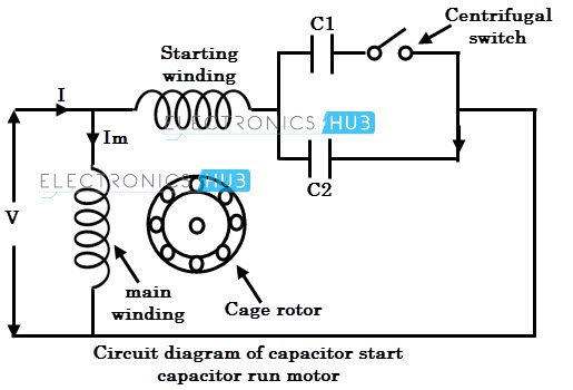
At starting, both starting and running capacitors are connected in series with the auxiliary winding. Thus the motor starting torque is more compared with other types of motors.
Once the motor reaches some speed, the centrifugal switch disconnects the starting capacitor and leaves the running capacitor in series with auxiliary winding.
Thus, both running and auxiliary windings remain during running condition, thereby improved power factor and efficiency of the motor.
These are the most commonly used single phase motors due to high starting torque and better power factor. These are used in compressors, refrigerators, air conditioners, conveyors, ceiling fans, air circulators, etc.
Shaded Pole Induction Motor
This motor uses entirely different technique to start the motor as compared with other motors so far we have discussed now.
This motor doesn’t use any auxiliary winding or even it doesn’t have a rotating field, but a field that sweeps across the pole faces is enough to drive the motor. So the field moves from one side of the pole to another side of the pole.
Although these motors are of small ratings, inefficient and have low starting torque, these are used in a variety of applications due to its outstanding features like ruggedness, low initial cost, small size and simple construction.
A shaded pole motor consists of a stator having salient poles (or projected poles), and a rotor of squirrel cage type. In this, stator is constructed in a special way to produce moving magnetic field.
Stator poles are excited with its own exciting coils by taking the supply from a single phase supply. A 4-pole shaded pole motor construction is given in below figure.
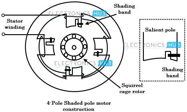 Each salient pole is divided into two parts; shaded and un-shaded. A shading portion is a slot cut across the laminations at about one third distance from one edge, and around this a heavy copper ring (also called as shading coil or copper shading band) is placed.
This part where shading coil is placed is generally termed as shaded part of the pole and remaining portion is called as un-shaded part as shown in figure.
Let us discuss how the sweeping action of the field takes place.
When an alternating supply is given to the stator coils, an alternating flux will be produced. The distribution of flux in the pole face area is influenced by the presence of copper shading band.
Let us consider the three instants, t1, t2, and t3 of alternating flux for an half cycle of the flux as shown in figure.
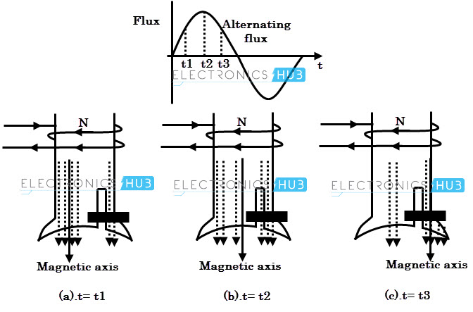
- At instant t= t1, the rate of change of flux (rising) is very high. Due to this flux, an emf is induced in the copper shading band and as the copper shading band is shorted, current circulates through it. This causes current to create its own field.According to Lenz’s law, the current through copper shading band opposes the cause, i.e., rise of supply current (and hence rise of main flux). Therefore the flux produced by shading ring opposes the main flux. So there is weakening of flux in the shaded part while crowding of flux in un-shaded part. So the axis of overall flux shifts to non-shaded part of the pole as shown in the figure.
- At instant t=t2, the rate of rise of flux is almost zero, and hence very little emf is induced in the shaded band. It results negligible shaded ring flux and hence there is no much affect on distribution of main flux. Therefore, the distribution of flux is uniform and the overall flux axis lies at the center of the pole as shown in figure.
- At instant t=t3, the rate of change of flux (decreasing) is very high, and induces emf in copper shading band. The flux produced by the shading ring is now opposes the cause according to Lennz’s law. Here, the cause is decreasing flux, and opposing means its direction is same as that of main flux. Hence, this flux strengthens the main flux. So there will be crowding of flux in the shaded part compared to the non shaded part. Due to this overall flux axis shifts to the middle of shaded part.This sequence will repeat for negative cycle too and consequently it produce moving magnetic field for every cycle from non shaded part of the pole to shaded part of the pole. Due to this field, motor produces the starting torque. This starting torque is low about 40 to 50 percent of full load torque. Therefore, these motors are used in low starting torque applications such as fans, toy motors, blowers, hair dryers, photocopy machines, film projectors, advertising displays, etc.
Image Credits
- Induction Motor : zjidealmotor.com
- Single Phase Induction Motor : img.diytrade.com
- Split Phase Induction Motor : guideimg.alibaba.com
- Capacitor Start Induction Motor : img.diytrade.com
- Permanent Capacitor Induction Motor : fuanshengke.com
- Capacitor Start and Capacitor Run Induction Motor : static.grainger.com

5 Responses
Thanks….
Best understood
Its wonderful
Very comprehensive. Thanks
The split phase motor may also have a electromagnetic start switch. (Relay) normally open contacts for the auxiliary windings. The high current load in the primary windings pulls the switch contacts closed, allowing power into the auxiliary windings. Once up to operating speed, the current is lower and the contacts go open thereby disconnect the start windings. If the contacts become fused then the auxiliary windings burn up. I found this out after my belt sander motor started smoking.
Hopefully this may help someone.