In this tutorial, we will learn how to upload a program to Raspberry Pi Pico using SWD and also debug with SWD. Till now, we have been using drag-and-drop method for uploading program to Pico. But if you want to use SWD Interface of Pico to program and debug, then this tutorial is for you. Learn the steps for Programming Raspberry Pi Pico with SWD and also debugging the code with SWD, OpenOCD and GDB.
A Brief Note on SWD
Have you ever worked on developing an Embedded System Application? If the answer is yes, then you might be familiar with the term ‘Debugging’. In embedded systems, which are mainly designed with a single task (or a very small number and specific set of tasks) in mind, the process of debugging and testing is very critical as we often work as low as CPU Register level.
There are several hardware and software solutions for debugging embedded systems. One such offering is called Serial Wire Debug or SWD in short. SWD is a Debug and Trace Port embedded into the silicon of most modern ARM based Microcontrollers and Microprocessors.
Using a SWD Probe (a small hardware often connected to SWD Port of the Microcontroller and maps them to USB) you can program the Flash of the Microcontroller, Debug the Firmware, Add Breakpoints, Stepping through the Code, etc. with just two wires.
The combination of SWD, GDB (GNU Debugger) and OpenOCD (an on-chip debugger which supports debugging, in-system programming and boundary scan for embedded systems) is a very powerful debugging setup, especially for ARM Cortex series of Processors.
Raspberry Pi Pico SWD Programming and Debug
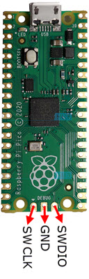
Like all ARM Cortex processors, the Raspberry Pi Pico also has dedicated hardware for debugging via the SWD Interface. The two wires required for SWD Debugging are called SWDIO (bidirectional SWD Data) and SWCLK (SWD Clock).
On the Raspberry Pi Pico, the SWD Pins are separated from the rest of the GPIO Pins and are placed at the bottom of the Board.
The 2-wire SWD Interface of RP2040 on the Raspberry Pi Pico board allows you to do the following:
- Upload program into External Flash or Internal SRAM.
- Control the state of execution of the processor i.e., run, halt, step, set breakpoints, etc.
- Access processors memory and IO peripherals (which are memory mapped) through the system bus.
Installing Tools in Raspberry Pi
As mentioned earlier, GDB and OpenOCD are required for debugging any ARM Cortex Processor. So, we will now install these two in our host system, which in my case is a Raspberry Pi running the latest Raspberry Pi OS.
OpenOCD
To understand the SWD Protocol and control the ARM Cortex Processor (two in case of RP2040), you need a special translator called OpenOCD. Let us now see how to install OpenOCD in Raspberry Pi.
NOTE: The following steps will install OpenOCD in /home/pi/pico/openocd.
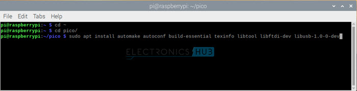
This will install all the tools require by OpenOCD. Next, we will clone the OpenOCD into our host and install OpenOCD. Enter the following commands one after the other.
I will take some time to build and install OpenOCD. Sit back and relax.
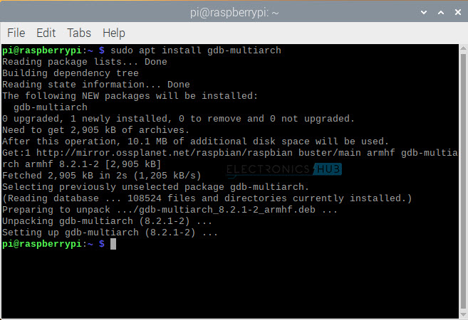
GDB
Next step is to install GDB. To install GDB Multi-Arch, use the following command:
We will see how to debug using OpenOCD and GDB in the next section.
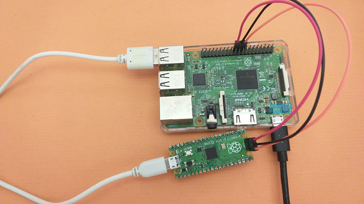
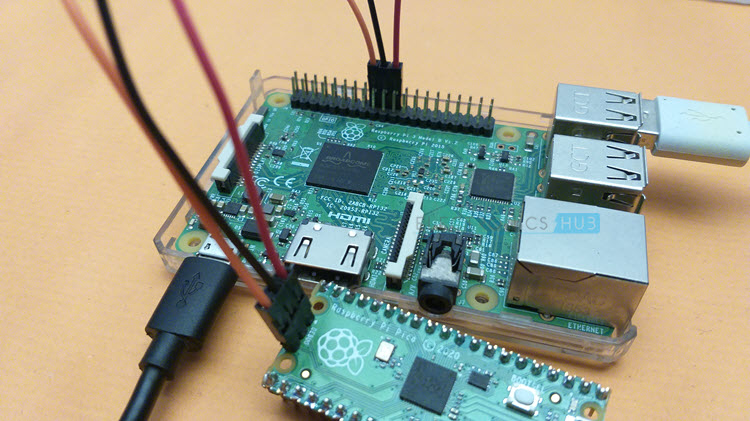
Wiring Raspberry Pi Pico and Raspberry Pi
Before see how to program Raspberry Pi Pico using SWD, you have to first properly wire the Raspberry Pi Pico.
IMPORTANT NOTE: I do not know the exact reason but before making the connections, I had to shutdown Raspberry Pi to successfully program Raspberry Pi Pico using SWD. I read in Raspberry Pi Forum that both the Raspberry Pi and the target i.e., Raspberry Pi Pico in this case must be powered down before connecting SWD pins.
Since Raspberry Pi Pico is connected to Raspberry Pi through USB (to power it up), all I had to do was shutdown Raspberry Pi, make the SWD Connections and then power on Raspberry Pi.
The following table shows all the necessary connections between Raspberry Pi and Raspberry Pi Pico that you need to make.
|
Raspberry Pi Pico |
Raspberry Pi |
| SWDIO |
GPIO 24 (PIN 18) |
|
SWD GND |
GND (PIN 20) |
| SWCLK |
GPIO 25 (PIN 22) |
Programming Raspberry Pi Pico with SWD
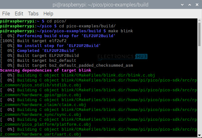
Let us use the ‘Blink’ program as an example to understand how Raspberry Pi Pico SWD Programming works. If you remember in the ‘Programming Raspberry Pi Pico with C’ tutorial, we already built the Blink program, which resulted in a few target files.
For drag-and-drop programming via USB, we used the .uf2 file. But OpenOCD uses .elf file to upload the program.
Use the following commands to Program Raspberry Pi Pico with SWD.
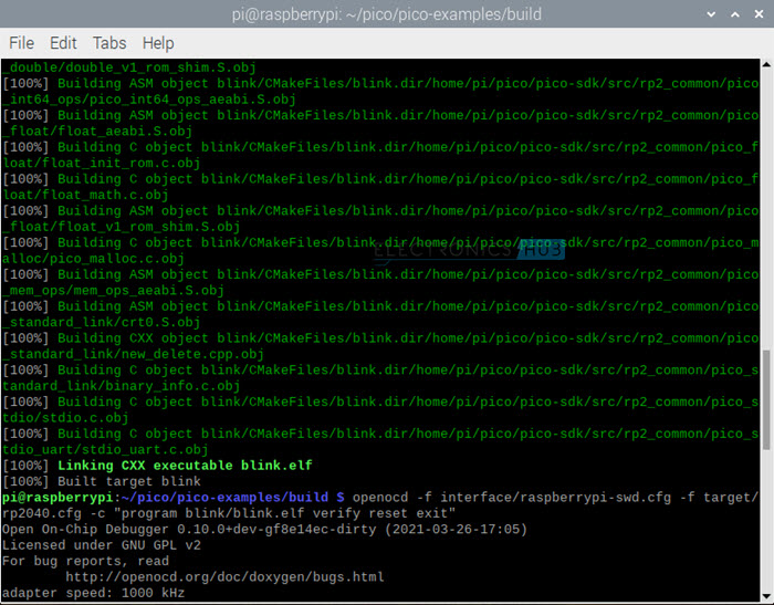
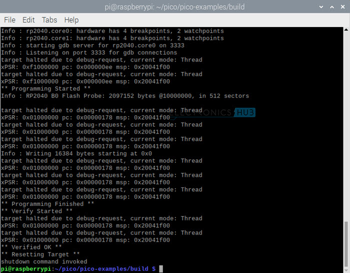
The above command will invoke OpenOCD to program the blink.elf file to Raspberry Pi Pico, reset the board and exit the OpenOCD. If everything goes well, your terminal should display something like this and the LED on Raspberry Pi Pico should start to blink.
Debugging Raspberry Pi Pico with SWD
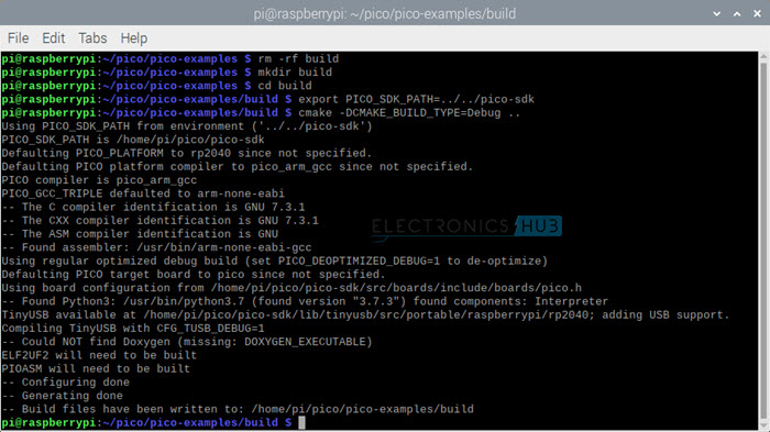
Let us now see how to debug the code suing SWD, OpenOCD and GDB. We already installed GDB in the previous step. Now, to include the debug related settings in the build files, you have use the CMake directive ‘ -DCMAKE_BUILD_TYPE=Debug ’.
But before that, you need to remove the ‘build’ directory from ‘pico-examples’ directory and create a new ‘build’ directory. Use the following commands to build examples with Debug information.
Let us use the ‘hello_world’ example and build for the serial variant. You cannot use USB based serial connection for SWD Debugging as the USB Device will be disconnected when stopping the processor core in debugging.
Also, the connections between Raspberry Pi Pico and Raspberry Pi to view the output of Raspberry Pi Pico’s UART Serial Output on Raspberry Pi is as follows:
|
Raspberry Pi Pico |
Raspberry Pi |
| GPIO 0 (UART0_TX) |
GPIO 15 (UART_RX0) PIN 10 |
|
GPIO 1 (UART0_RX) |
GPIO 14 (UART_TX0) PIN 8 |
| GND |
GND (Pin 14) |
After making the connections, open the hello_world UART directory and build it.
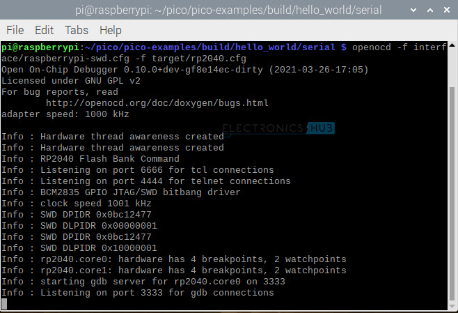
Use OpenOCD to open the GDB Server.
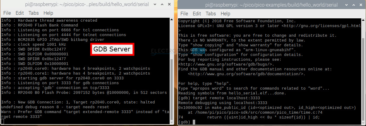
Keep this terminal as it is and open another terminal window and browse to UART Serial directory in the build directory.
Open GDB and connect to OpenOCD Server.
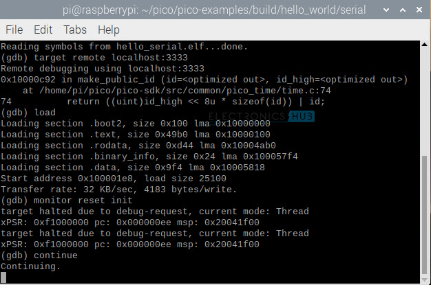
To load the program into the flash memory of Raspberry Pi Pico, use load command.
Start running the code.
If you are familiar with GDB commands, you can explore them.
Conclusion
A complete tutorial on Programming and Debugging Raspberry Pi Pico with SWD. Learn how Raspberry Pi Pico SWD Interface works, the necessary connections between Raspberry Pi Pico and Raspberry Pi for SWD, program Raspberry Pi Pico with SWD, use GDB to debug Raspberry Pi Pico using SWD.

6 Responses
Thanks for this.
Just to let you know there is a typo in the table that says how to connect SWD to the Pico.
GPIO 24 (PIN 18) and also GPIO 25 (PIN 18)
I updated the pins. Thank you.
Is it possible to use an ST-LINK for SWD? I don’t happen to have a Raspberry Pi lying around.
Technically, it should be possible but not directly with st link firmware. You have to flash a different firmware (Segger’s J Link or Black Magic Probe). I personally haven’t tried this.
This is an excellent procedure, one of the things that I had trouble with was that the SWD connection worked only once in a while for me. I solved the problem by finding the shortest wires between pi and pico possible. It’s possible maybe my original wires were a problem but it seemed reasonable to use short wires because of the high bandwidth. I’ve seen other setups that use ribbon connectors, perhaps twisted pair would work better as well. The wires I have now are about 3 inches and I have no problems at all connecting.
Hi
Can you do a video using a desktop pc running RPIOS.