The primary function of a motor starter is to start and stop the motor to which it is connected. These are specially designed electromechanical switches similar to relays. The main difference between a relay and a starter is that a starter contains overload protection for the motor. So the purpose of the starter is twofold, i.e., to switch the power automatically or manually to a motor and at the same time protect the motor from overload or faults.
Motor starters are available in different ratings and sizes depending on the motor’s (AC motor) rating and size. These staters safely switch the necessary power to the motor and also prevent the motor from drawing heavy currents. Let us see more details about the need for a Motor Starter, different types of Motor Starters and also their wiring diagrams. In this article we are going to deal only with AC motor starters, as they are the work horses in industries and commercial applications.
Why Motors Need a Motor Starter?
A stator is needed for an induction motor (three phase type) in order to limit the starting current. In a three phase induction motor, the rotor induced emf is proportional to the slip (it is the relative speed between stator and rotor) of the induction motor. This rotor emf drives the current through the rotor.
When the motor is at standstill condition (at the start), the speed of the motor is zero and hence slip is at maximum. This induces very high emf in the rotor at starting condition and thereby a very high current flows through the rotor.
As the rotor needs a high current, stator winding draws a very high current from the supply. This initial drawing current can be of the order of 5-8 times the full load current of the motor.
This huge current at the starting of a motor can damage the motor windings and also this current can cause a large voltage drop in the line.
These voltage spikes may affect the other appliances connected to the same line. Therefore, a starter is necessary to limit this starting current to avoid damage to the motor as well as to other adjoining equipment.
A starter is a device that reduces initial high current of the motor by reducing the supply voltage applied to the motor. Such reduction is applied for very short duration and once the motor accelerates, slip value decreases and hence a normal voltage is then applied.
In addition to the starting current protection, motor starter also provides the protection against overload, single phasing and low voltage protection.
The overload protection is necessary because motor draws more current during overload condition and it causes to produce excessive heat in the windings. This extra heat reduces the motor’s life and may cause burning of windings and hence fire.
All starter devices are provided with some overheating protection element to limit high current during overload. Most of these devices work on timed overload concept in which overload current is allowed for a short time (very few seconds) and then stops the motor if the current exists for beyond that time.
Most starters are equipped with bimetallic strips to achieve this operation.
Some motors that are rated below 5 HP are directly connected (using DOL starter) without reducing the supply voltage (at initial condition), but they are provided with overload, low voltage protection and single phasing protection. This is because such motors can withstand high starting current for short duration.
How a Motor Starter Operates?
Basically, a starter is a switching device that consists of electrical contacts (both incoming and outgoing). Based on the operation, starters are primarily divided into hand operated and electrically operated devices.
Hand operated starter consists of a lever on the side of it that can be turned on or off. Usually these are used for smaller motors as they are incapable of operating remotely.
This type of motor starters causes the motors to restart immediately after a power interruption. This instant operation of the motor after power failure may leads to flow of dangerous currents into the motor and hence the motor will be damaged. This is the reason why most of the starters are equipped with electrical switches.
In case of electrically operated starters, electromechanical relays are used for switching the power carrying conductors. These relays are called as contactors. When the coil in the contactor is energized, it produces the electromagnetic field and that pulls the switch contacts.
And when the coil is de-energized, contacts are pulled back to normal position by the spring arrangement. Usually, the motor starters are provided with push buttons (start and stop buttons) in order to energize and de-energize the coil so that contacts will be operated. These electrically operated starters will not restart after a power failure until the start button is pressed.
Different Techniques used in Motor Starters
Most of the industrial operation uses three-phase induction type motors as compared to any other type of motor. There are different techniques used to start a three-phase induction motor. Before knowing various types of starters, let us first discuss about the techniques used for induction motor starters.
Full Voltage Technique
This method often referred as direct on-line (DOL) starting and it is the most common way of starting three-phase induction motor. In this technique, a full voltage (or rated voltage) is applied across the motor as it is inherently a self starting motor that requires full voltage to start it.
This technique is applied only for a motor which are rated less than 5HP as described above. The motor starters employing this method are called DOL starters.
Reduced voltage technique: This method is employed for large motors rated in the range of 100HP and above (or for a motor that takes very high starting currents). As discussed earlier that, these high rated motors draw a very high starting currents and also may cause voltage drop in the line.
In such cases reduced voltage technique is used, where voltage to the motor is reduced initially for a few seconds until the motor rotates and then applied voltage is increased to its rated supply voltage thereby motor rotates to its rated speed.
Motor starters employing the technique of reducing voltage are called reduced voltage starters. Commonly used reduced voltage starters include stator resistance starter, auto transformer starter and start-delta starter.
Bidirectional Starter Technique
In some processes, it is necessary to operate the motor in both forward and reverse directions. Generally, three-phase motor direction can be reversed by changing any two wires (i.e., altering the sequence of RYB) of the three phase supply.
In this method, two contactors are employed with suitable connection and interlocking mechanism between them in order to achieve bidirectional operation.
Multispeed Technique
In this method, motor starters are made to deliver different voltages to the motor for operating the motor at different speeds.
Typically, these starters are designed to operate the motor at two or three different speeds using two or more contactors. Most of these starters are made with full and reduced voltage versions.
Types of Motor Starters
Based on the above techniques, the most common types of starters are listed below.
- Stator Resistance Starter
- Auto Transformer Starter
- Star-Delta Starter
- Direct on-line Starter
- Soft Starter
These motor starters are discussed in detail in the following section.
Stator Resistance Starter
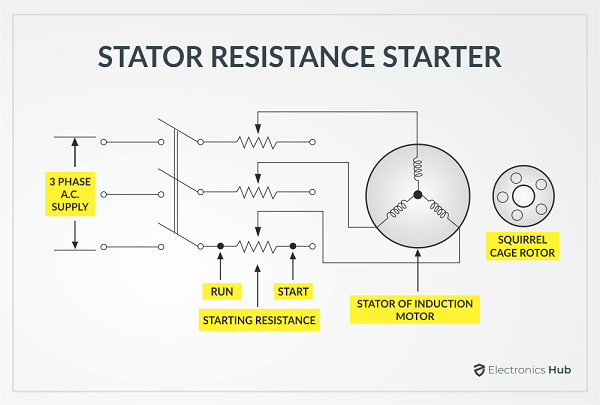
In this method, a reduced voltage is applied to the induction motor by connecting external resistances in series with each phase of the stator winding.
During the motor start, these resistances are kept at maximum position such that a reduced voltage is applied across the motor due to large voltage drop across resistances. The schematic diagram for this type of starter is shown in figure below.
Once the motor picks up the speed, the resistance connected to each phase is gradually reduced from the stator circuit. When these resistances are removed from the circuit, a rated voltage (full voltage) is applied to the motor and hence it runs at rated speed.
In this method, it is important to maintain the starting torque to the motor while minimizing the starting current. This is because current varies in proportion to the voltage whereas the torque varies square of the applied voltage.
Suppose if the applied voltage is reduced by 50 percent, the current will be reduced to 50 percent while the torque reduced by 25 percent.
The construction of this starter is simple and it is the most economical method than all methods. Also, this starter can be used for motor whether they are a star or delta connected. However, due to high power dissipation in the resistors, a large power loss takes place in the motor.
In addition, a reduced voltage causes a reduced torque at start of the motor. Due to these limitations, resistance method is limited for some applications.
Auto Transformer Starter
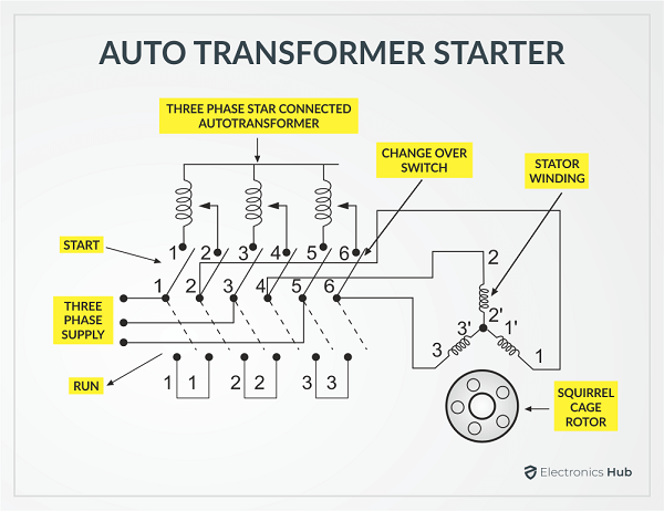
In this method, a three-phase auto transformer is connected in series with the motor. This transformer reduces the voltage applied to the motor and hence the current. The schematic diagram for this type of starter is shown in figure below.
This starter consists of changeover switch that switches the motor between reduced voltage and full voltage conditions. When this switch is in the start position, a reduced voltage is applied to the motor.
This voltage depends on the fractional percentage of tapings and is controlled by changing the position of autotransformer slider.
When the motor attains 80 percent of its rated speed, the changeover switch is connected to RUN position automatically using relays. Due to this, a rated voltage is then applied to this motor. These transformers are , also provided with overload, no-load and time delay circuits.
In this method, the motor terminal voltage is higher for a given starting current on the line side as compared to other reduced voltage methods. Therefore, this method gives highest starting torque per line ampere current.
This stator can be connected to both star and delta connected three –phase motors. However, these starters are more expensive than stator resistance starter.
Star Delta Starter
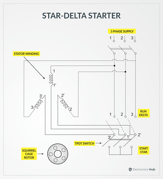
The Star Delta Starter is the most commonly used reduced voltage starter as it is the cheapest starter among all. In this method, induction motor is connected in star during start and delta while running with rated speeds.
These starters are designed to run on delta connected stator of an induction motor. The schematic diagram of this starter is shown in figure below.
This starter uses a TPDT (triple pole double throw) switch and it connects the stator winding in star during the starting condition. Due to this star connection, the applied voltage to the motor is reduced by the factor 1/√3. This reduced voltage results the less current through the motor.
When the motor picks up the speed, the TPST switch is thrown automatically on the other side by using relays such that the winding is now connected in delta across the supply. So the normal voltage is applied to the motor (because in delta connection voltage is same, VL =VP) and hence the motor runs at normal speed.
This method is cheap and maintenance free as compared to other methods. However, this is suitable only for delta connected motors and also the factor by which starting voltage reduced, i.e., 1/√3 cannot be altered.
Direct On-Line Starter
As discussed earlier that small capacity motors (below 5 HP) doesn’t have very high starting currents. And without using any starter, such motors can withstand the starting currents.
There is no need to reduce the voltage to the motor at start and hence motor can be connected directly to the supply lines. This type of arrangement employed in a starter is referred as direct on-line starter or simply DOL starter.
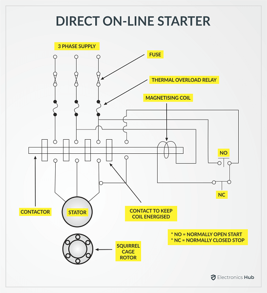
Although, this starter does not reduce the starting voltage, it provides the protection to the motor against overloading, single phasing and low voltage. The schematic diagram of direct online starter is shown in figure below.
During start condition, normally open contact (NO) is pushed for fraction of a second and this makes the magnetizing coil becomes energized. This magnetic flux produced by the coil attracts the contactor so that the motor is now connected to the supply.
The contactor maintains this position while the coil gets supply from the additional switch. When a normally closed (NC) switch is pressed, the coil becomes de-energized and the contactor get separated by spring arrangement there by the supply to the motor is removed.
Under any overload condition, motor draws a heavy current that causes overheating. This excessive heating operates the thermal relays using overload sensors. Overload contacts then operates to remove the supply to the motor.
It is the simplest, cheapest and most reliable method and hence widely used. The main disadvantage of DOL starter is that the motor draws a very high current during start for a short period.
Soft Starter
In this method, semiconductor power switches are employed for reducing the starting current to the induction motor. It is another type of reduced voltage starter and it connected in series with the line voltage applied to the motor. The schematic diagram of soft starter is shown in figure below.
This starter consists of back to back thyristors or TRIACs in each phase of the stator winding. By controlling the firing angle to these thyristors, the voltage applied to the motor will be reduced stepless. This type of voltage reduction gives a smoother operation as compared to other methods discussed above.
This results the absence of torque pulsations and hence there no jerking when starting of the motor. Once the motor gets the normal speed, the firing angle to the thyristors is applied such that they allow full voltage to the motor.
For larger motors, a variable frequency drives are used that incorporates the soft start function. Such drives control the starting current as well as the speed of the motor to a desired value.
These starters are also provided with additional protections, such as overload, low voltage and single phasing.
Conclusion
A introductory guide of Motor Starters. They are an essential part of modern motor drives for a safe and protective operation of motors. We learned about the need for a Motor Starter, Different Types of Motor Starters and also the wiring diagrams of some popular motor starter techniques.

One Response
Great! So educative, to the world of electronics/electrical engineering .