A tunable type of oscillators is required for some of the wireless applications for which the output frequency is a function of the input. Most commonly a voltage signal is used as control input to vary the output frequency. These type of oscillators are called as Voltage-controlled oscillators or simply VCO.
Most commonly these are used in pulse modulators (AM), frequency modulators (FM) and phase locked loops. The frequency is varied by controlling electronically a voltage-dependant capacitance of the resonant circuit RLC. Let us discuss brief on this concept.
Frequency Control in VCO
VCOs take many forms, it can be some type of LC or crystal oscillator, or it can be some type of RC oscillator or multivibrator. The below figure illustrates the basic operation of a VCO.
For an RC type oscillator, the frequency of oscillations is inversely proportional to the capacitance (f = 1 / (2πRC)) and for LC oscillator the frequency of oscillations is 1 / (2π√LC). Therefore, as the reverse or control voltage increases the capacitance decreases. Thus the increase in control voltage increases the frequency of oscillations and vice-versa.
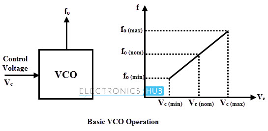
In the above figure, the oscillator running at its normal or free-running frequency at nominal control voltage Vc. The frequency increases with increase in control voltage above the nominal value and the frequency decrease with decrease in Vc below the nominal voltage.
For achieving this variable voltage, variable capacitance diodes, varactors are used which are available at different range of capacitance. Alternative methods like , changing the charging rate of capacitor , with the help of a voltage controlled current source are implemented for low frequency oscillators.
Types of Voltage Controlled Oscillators
According to the type of waveform produced voltage controlled oscillators are categorized into two groups namely harmonic oscillators and relaxation oscillators.
Harmonic Oscillator
Harmonic or linear voltage controlled oscillator produces the sinusoidal output waveform. Crystal and LC oscillators are the examples of this type of VCO. In this VCO, voltage across the diode varies the varactor diode’s capacitance. Hence the varactor changes capacitance of the LC circuit thereby the frequency changes.
With respect to the power supply, temperature and noise frequency stability is much better for these oscillators compared with relaxation oscillators. But the disadvantage of this oscillator is that it cannot be implemented easily on a monolithic IC.
Relaxation Oscillator
These VCOs are used to generate a triangle or sawtooth waveform. These can be easily implemented on monolithic ICs which can be tunable over a wide range of frequencies. These oscillators again classified into emitter coupled VCO, grounded capacitor VCO and delay based ring VCO.
The most common use of VCOs is of two forms namely VCO as an astable multivibrator and VCO as a Schmitt trigger.
In case of astable multivibrator VCO, the capacitance charging current on either side of the multivibrator is proportional to the external input voltage. Depending on the capacitor value in the multivibrator frequency range is selected.
Square wave is the output of this type of oscillator. This scheme is simple in operation, less costly and works with low power supply currents.
Another common form of VCO is essentially built with comparator, integrator, switch and a Schmitt trigger. A timing capacitor charges over a definite voltage range by a buffer inside the VCO IC. This charging current is proportional to the modulation voltage.
Once the threshold level is reached, the capacitor stops charging and starts discharging. Hence the cycle of charging and discharging produces a periodic output which not in the form of square type.
VCO Working Principle
A wide variety of circuit designs can be made to implement a voltage controlled oscillator using different voltage control electronic components like transistors, varactor diodes, Op-amps, etc. The figure below shows a simple voltage control oscillator using astable multivibrator.
In this a time constant resistors R1 and R2 brought out to an external control line Vcontrol. The voltage to which C1 and C2 discharges through R1 and R2 changes with change in Vcontrol voltage. Hence the discharging speed is increases with increase of Vcontrol.
This arrangement changes the base voltage to which the base of the transistor must climb or descend. Therefore, by these RC elements and tun ON or OFF of the transistors alter the operating frequency of oscillations at the output.

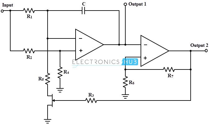
The other form of circuit for a voltage controlled oscillator is shown below which is implemented by using two operational amplifiers. It generates the square wave at the output whose frequency is determined by a control voltage. The first op-amp works as an integrator.
The control voltage is applied at the input terminal and due to the voltage divider arrangement, half the control voltage is applied at the positive terminal of the first op-amp. Also, at the negative terminal, the voltage is maintained at the same level in order to maintain the voltage drop across the R1 is half the control voltage.
When the MOSFET is turned ON, the current from the resistor R1 flows through the MOSFET. The voltage which is now converted into current signal charges the capacitor. Therefore, to source this current, the first op-amp must provide a steadily rising output voltage.
When the MOSFET is turned OFF, the current flows from the R1 and hence discharges the capacitor. Therefore from the first op-amp falling output voltage is needed. Thus the output of the first op-amp is a triangular waveform.
The second op-amp works as Schmitt trigger and it accepts the triangular wave as input from the first op-amp. When the input voltage is above the threshold level, then it outputs Vcc at its output and if the input falls below the threshold level, the output becomes zero. Hence the square wave output is produced at the output.
Voltage Controlled Oscillator Using LM566
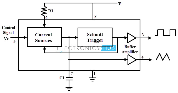
A LM566 is a voltage controlled oscillator IC unit which is built with internal circuitry to generate both triangular and square wave signals whose frequency is set or adjusted by external capacitor and resistor followed with an application of DC voltage.
The figure below shows the block diagram of LM566 IC in which current sources charge and discharge the external capacitor at its rate set by the resistor R1 and also controls the DC input voltage. For switching the capacitor between charging and discharging, a Schmitt trigger circuit is used as shown in figure.
The square wave voltage developed from Schmitt trigger and the triangular voltage across capacitor are provided as outputs through buffer amplifiers.
Phase Locked Loop
Voltage Controlled Oscillators are the important building block of Phase-locked loops. Phase clocked loops are the analog building blocks used in many digital and analog applications. These are used in clock recovery in many digital and communication systems, also used as frequency synthesizers in television and wireless communication systems to select various channels.
A PLL operates in such a way that the frequency and phase of a voltage controlled oscillator are synchronized with a second reference signal. It is an electronic circuit that consists of a voltage controlled oscillator, low pass filter and a phase detector as shown in figure. It is capable of synchronizing or locking with an incoming signal.
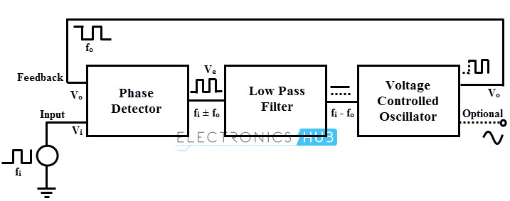
Whenever the frequency of the incoming signal changes, the phase comparator compares frequency of the input with that of oscillator output signal and produces the phase difference signal.
This output is filtered in low pass filter and produce the filter output as Vcontrol to control the frequency of the VCO until the frequency and phase difference becomes zero. At this point the PLL is locked or synchronized to the input frequency. PLLs are used mostly in frequency synthesis and frequency modulation applications.
Applications of VCO
- Tone Generators
- Function generators
- Phase-Locked Loops
- In synthesizers to generate variable tones for the production of electronic music
- In communication equipment these are used as frequency synthesizers
- Clock generators
- Frequency Shift Keying

One Response
I only read half of the article. It has many errors.
¡ Thank you so much !