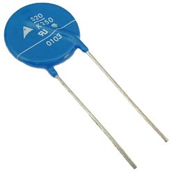
Varistor is portmanteau of variable resistor. It is a passive non linear two terminal solid state semiconductor device.
A Varistor, or Voltage Dependent Resistor (VDR), is a type of resistor whose resistance changes with the voltage applied across it. It’s used to protect circuits against high voltage spikes. When the voltage is low, a varistor has high resistance, which means it won’t affect the circuit much. But if a high voltage spike occurs, the varistor’s resistance drops dramatically, allowing it to absorb the excess energy and protect the components in the circuit. This makes varistors an essential component in surge protection devices, helping to safeguard electronic equipment from voltage surges that can be caused by lightning strikes, power outages, or other electrical disturbances.
Varistor Voltage Dependent Resistor
Varistor provide over voltage protection to electrical and electronic circuits in contrast to circuit breakers or fuse which provide protection to circuits from over current. Varistor provide protection by voltage clamping method which is similar to that in a Zener Diode.
Even though the name varistor is derived from the terms variable resistor, the resistance in varistor can’t be varied manually unlike potentiometer or rheostat where the resistance can be varied manually between their maximum and minimum values.
The resistance of a varistor is varied according to the voltage applied to it. The change in voltage across a varistor will result in change of its resistance, making it a voltage dependent device. Hence the varistor is also called Voltage Dependent Resistor (VDR).
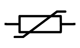
The two standard symbols of varistor are shown below.
IEEE standard symbol for varistor
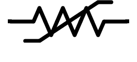
IEC standard symbol for varistor
Generally , varistors are made from semiconductor materials. The voltage and current characteristics of a varistor are non linear in nature. Also the voltage and current characteristics of a varistor are suitable for both DC and AC supplies.
Physically, a varistor looks like capacitor in many ways. Because of the resemblance, a varistor is often confused to a capacitor. However, application wise, a capacitor can’t prevent from voltage surges that a varistor can.
The results of an accidental high voltage surge to any circuit can be catastrophic. Hence the use of varistor in the protection of delicate and sensitive electrical or electronic circuits from high voltage surges and switching spikes is very important.
Resistance of a Varistor
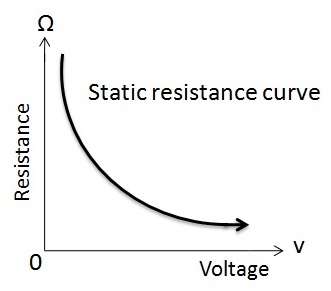
Even though the aim of the varistor is to provide resistance, the operation of a varistor is different from a potentiometer or rheostat. The resistance of a varistor is very high under normal operating conditions.
The functionality of varistor is similar to that of a Zener diode where it allows voltages of lower threshold to pass unaffected.
The functionality of a varistor changes at high operating voltages.When the voltage applied across a varistor is larger than that of its rated value, the effective resistance of the varistor falls drastically and it continues to decrease as the voltage applied to it increases.
The curve representing the static resistance of the varistor with respect to its applied voltage is shown below.
V-I Characteristics
According to Ohm’s law, the current-voltage characteristics curve of a resistor is a straight line, assuming the value of the resistor is kept constant. In this case, the current flowing through a resistor is directly proportional to the voltage applied across the ends of resistor.
In case of a varistor, the current-voltage characteristics curve is not a straight line. This is because of the unusual resistance behavior of the varistor. In case of a varistor, a small change in the voltage applied to it will cause a sufficiently great change in the current flowing through it.
The current voltage characteristics curve of a varistor is shown below.
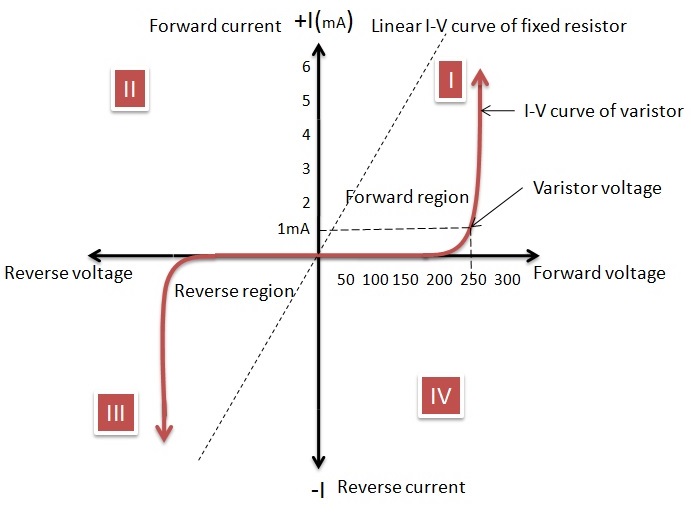
From the current-voltage characteristic curve shown above, it is clear that a varistor has bi directional symmetrical characteristics. This means that the varistor can operate or function in either directions or polarities of a sine wave. This functionality of a varistor is similar to that of back to back connected Zener diodes.
The current-voltage characteristic curve of a varistor shows a linear relationship between current and voltage when the varistor is not conducting. This is because the current flowing through the varistor will remain constant and the value is very low.
This is the leakage current in the varistor and the value of this current is in the order of very few milli amperes. The reason for this is the high resistance of the varistor. This small current will remain constant until the voltage applied across the varistor reaches the rated voltage of the varistor.
The rated voltage of the varistor is also called as Clamping voltage. The rated voltage of a varistor is the voltage across it which is measured with a specified DC current of 1mA .This further can be explained as the DC voltage applied across the terminals of the varistor that allows a current of 1 milli Ampere to flow through it.
The current flowing through the varistor body is dependent on the material used for the construction of the varistor. At this rated voltage level, the functionality of the varistor begins to change.
Until the rated voltage, the varistor acts as an insulator. If the applied voltage of varistor reaches its rated voltage, the behaviour of the varistor changes from insulating state to conducting state.
The resistance of the varistor becomes very small when the transient voltage applied across the varistor is greater than or equal to the rated voltage of the varistor. This is because of a phenomenon called Avalanche Breakdown in semiconductor materials.
Avalanche breakdown is a form of current multiplication that allows large currents in the materials which are previously acting as insulators. Due to this situation the small current flowing through the varistor which is the leakage current will quickly rise.
Even though the current flowing through varistor rises, the voltage across it is limited to a value just near to the rated voltage of the varistor. This means that the varistor acts as a self-regulator to the transient voltages applied across it by passing or allowing more current to flow through the varistor.
Hence, after crossing the rated voltage of the varistor, the current-voltage curve becomes a steep nonlinear curve. Due to this feature, a varistor can pass extensively varying currents over a very narrow range of voltages by clipping off any spikes in voltage.
Capacitance in Varistor
When the applied voltage across the varistor is less than the rated or clamping voltage, a varistor acts as a capacitor rather than a resistor. The reason for this conclusion is that the behavior of the main conducting area of the varistor as a dielectric between the two terminals of the varistor.
The two terminals and the dielectric form a capacitor. This is valid until the voltage reaches the clamping voltage. Every varistor that is made up of a semiconductor material will have a capacitance value. This value depends on the area of the varistor and is inversely proportional to its thickness.
The capacitor behaviour of the varistor is different in DC and AC circuits. In DC circuits, the capacitance of a varistor exists when the applied voltage is below the rated voltage of varistor and it decreases abruptly when applied voltage near to rated voltage.
When a varistor is used in AC circuits, the frequency plays an important role. In AC circuits, when the varistor is operated in its non-conductive leakage region, the capacitance of the varistor will affect its body resistance.
The varistors are normally connected in parallel to electrical or electronic devices to protect them from over voltages.
Due to this, the leakage resistance of the varistor drops with an increase in the frequency. The relation between the frequency and the resulting parallel resistance is approximately linear. The AC reactance XC can be calculated using the formula
XC = 1 / (2 ×π × f×C) = 1/(2 πfC)
Here C is the capacitance and f is the frequency.
Hence as the frequency increases, the leakage current also increases.
Metal Oxide Varistor (MOV)
To overcome the limitations of semiconductor based varistors like Silicon carbide varistors, the Metal Oxide Varistors (MOV) have been developed. Metal oxide varistor is a voltage dependent resistor. It is also a non linear device and provides very good transient voltage surge protection.
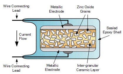
The resistance material in a metal oxide varistor mainly consists of Zinc Oxide grains that are pressed as a ceramic mass. The mixture consists 90 % of Zinc Oxide grains and the other 10 % is made with, other metal oxides like cobalt, bismuth and manganese.
This mixture is sandwiched between two electrodes (metal plates). The filler material acts as a binding agent to zinc oxide grains so that the component is kept intact between two metal plates. The connecting leads of a metal oxide varistor are radial leads.
Metal oxide varistors are the most commonly used components that are used as voltage clamping devices to protect small or heavy devices from transient voltage surges. Since a metal oxide is used in its construction, the ability to absorb short voltage transients and the energy handling capabilities are extremely high.
The operation of metal oxide varistor and silicon carbide varistor are very similar. A metal oxide varistor starts conducting current at rated voltage and it stops the conduction if the applied voltage is below the threshold value.
The main difference between a silicon carbide varistor and a metal oxide varistor is the amount of leakage current. The leakage current in MOV is very small at normal operating conditions.
The reason for lesser leakage currents can be explained as follows. In a metal oxide varistor, the two immediate neighbouring zinc grains will form a diode junction between their borders.
Hence a metal oxide varistor can be considered as a collection of huge number of diodes that are connected in parallel. Because of this, when a tiny voltage is applied between the electrodes, the reverse leakage current that appears across the diode junction is very small.
When the applied voltage increases and reaches the clamping voltage, the diode junction breaks due to avalanche breakdown and electron tunneling , and allows a huge current through it. Metal oxide varistors have high levels of non linear current voltage characteristics.
The maximum surge current a varistor can take will depend on the width of transient pulse and number of pulse repetitions. Typical widths of transient pulse are in the range of 20 microseconds to 50 microseconds.
There is a chance of overheating if the rated peak pulse current is insufficient. Hence, to avoid overheating of the circuit, it is important to quickly dissipate the energy that is absorbed from transient pulse.
High voltage surge protection
Whether the supply is AC or DC, transient voltage surges originate from many electrical sources and circuits regardless of the supply. This is because the transients are generated in the circuit or transmitted from external sources into the circuit.
Transients that are generated within the circuit can increase rapidly and may cause the voltage to increase to a value of several thousand volts. These voltage spikes may cause severe problems to sensitive electrical or electronic devices and hence must be prevented from appearing across them.
Some of the common sources of voltage transients are as follows:
- The voltage effect L di / dt (Ldi/dt) caused in inductive circuits. This effect is due to switching of inductive coils and magnetizing currents in transformers.
- Power supply surges.
- DC motor switching.
A varistor is connected across the mains supply to avoid voltage transients. This connection can be either between phase and neutral or between phase and phase in case of AC supply.
In case of DC supply, the varistor is connected across the supply between positive and negative terminals. In DC electronic circuits, the varistor can be used for voltage stabilization to protect from over voltage pulses.
Varistor Specifications
The following are the specifications of a typical varistor.
Maximum working voltage: It is the peak steady state DC voltage or sinusoidal rms voltage that can be applied continuously at a specified temperature.
Varistor voltage: It is the voltage between the terminals of the varistor with a specified DC measuring current applied.
Clamping voltage: It is the voltage between the terminals of varistor with specified impulse current applied to obtain peak voltage.
Surge current: The maximum current that flows through the varistor.
Maximum Energy: The maximum energy that is dissipated when an impulse of transient is applied.
Surge shift: The variation in voltage after giving the surge current.
Capacitance: Measured when the voltage is less than the varistor voltage.
Leakage Current: The current flowing through the varistor when it is in non-conducting state.
Response Time: The time between the application of rated voltage and transition from non-conducting state to conducting state.
Varistor Applications
Varistors are used in almost all heavy electrical circuits to small electronic designs. Varistors provide high voltage surge protection for both AC and DC circuits.
Some of the applications are
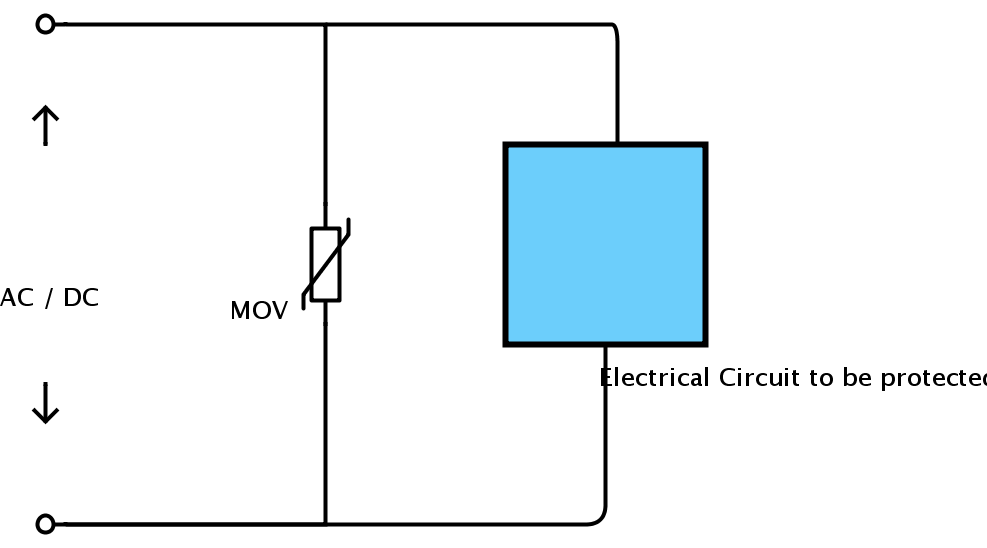
- To protect electrical circuits from over voltages. The following circuit shows a connection of metal oxide varistor to provide single phase line to line protection.
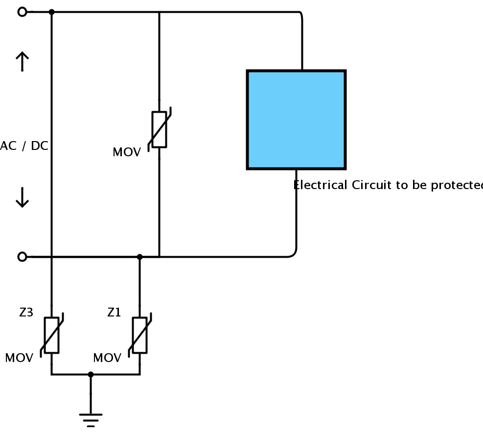
The following circuit is similar except that it also provides line to ground protection.
2.In electronic circuits, the devices are very sensitive to changes in voltage. Hence varistor is used. The following circuit is to show a typical varistor protecting a transistor.
![]()
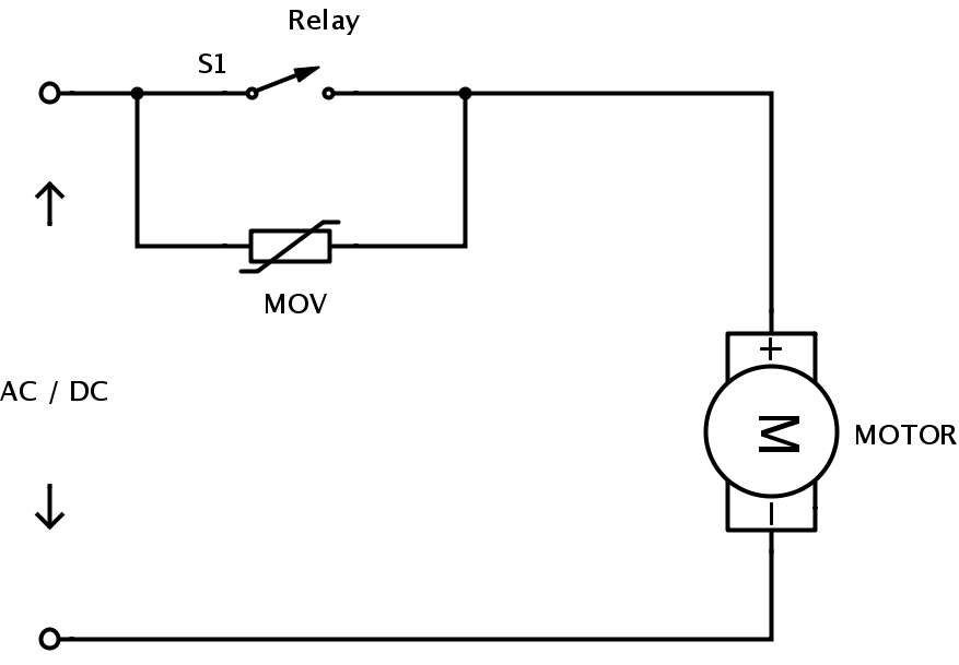
3.To provide surge protection to AC or DC motors.
Varistor Limitations
When a varistor is used in transient voltage surge suppressor, it may not provide power protection to the device. This is because the presence of a varistor in this situation will cause problems to equipment and the device itself.
Varistor cannot provide protection from the following
- Current surges during device start up
- Current from short circuit.
- From voltage sags or brownouts.

2 Responses
Helped me a lot. Thank you.
Can you explain why VDRs are always shown connected in parallel with the relay contacts, rather than in parallel with the inductive load?
I read that a common VDR failure mode is closed circuit so connecting in parallel with relay contacts seems unwise at first sight.
Why would it not be just as effective, and safer, to connect the VDR in parallel with the load?