An Uninterrupted Power Supply (UPS) is a crucial component in maintaining power continuity for electronic devices during power outages. It provides a backup power source that allows for the safe shutdown of computers and keeps vital systems operational. UPS systems vary in size and capability, from small units designed to protect individual PCs to large systems that safeguard entire data centers or buildings. They not only guard against power loss but also protect against voltage surges and fluctuations, ensuring the longevity and reliability of connected devices.
What Is Uninterrupted Power Supply?
Uninterruptible Power Supply (UPS), as the name specifies, is an electrical equipment that provides power supply to sensitive electrical and electronic devices without any interruption even when there is a power outage. The common problems electricity supply utility are power failures, low voltages, blackouts, brownouts (temporary interruption), surges, etc.
The main aim of an uninterruptible power supply is to provide an instant backup during power failure or mains outage. But due to the above mentioned problems, a modern day uninterruptible power supply can not only provide uninterrupted power supply but also protects sensitive electronic devices, IT equipment and other electrical loads from the above mentioned problems.
Uninterruptible power supply continuously monitors the input power supply and provides a clean and consistent power. When an uninterruptible power supply is used with an IT equipment like a PC for instance, it not only protects the hardware but also the data as there is no interruption in the power supply.
There are three main configurations of an uninterruptible power supply. They are online, line – interactive and standby (or offline). An online uninterruptible power supply provides continuous power protection by making use of double conversion topology.
In line – interactive uninterruptible power supply, the battery acts as a backup but the mains supply is continuously monitored for fluctuations. An offline uninterruptible power supply is a basic configuration to provide backup. A circuit for an uninterruptible power supply is described here.
Uninterrupted Power Supply Circuit Diagram
Circuit Components
- Transformer(220V to 12V/2A)
- Bridge rectifier IC (GBPC 610)
- IN4001 diodes – D1,D2
- Capacitors
- C1 – 2 mF
- C2 – 100 nF
- C3 – 1 uF
- C4 – 0.1uF
- C5 – 0.01uF
- C6, C7 – 100 uF
- C8 1000 uF(Electrolytic)
- Resistors
- R1 220 ohms
- R2 4.7 k ohm
- R3 120 K Ohm
- R4, R5 27KOhm
- R6, R7, R8, R9 10 Ohm
- Inductors (L1, L2 100 mH)
- LM7812 (IC1)
- LM555(IC2)
- CD4013(IC3)
- IRF 540 MOSFET(Q1, Q2, Q3, Q4)
- Transformer (12V to 230 V / 5 A)
Component Description
LM 7812
It is a voltage regulator with a regulated output of 12V at 1A. We use LM 7812 in order to provide a constant, regulated source of power for the operation of uninterruptible power supply.
LM 555
It is a timer IC that can be used to produce high precision timing delays and oscillations. We use the 555 timer to generate square wave which acts as the basic alternating signal for the AC supply.
CD 4013
It is a Dual D flip – flop IC. It has two sets of independent D flip – flops with independent set, reset, data, Q and Q’ for each flip – flop. We use this IC to generate the non – inverting as well as the inverting alternating signal to give as input to the output transformer.
GBPC 610
It is a bridge rectifier IC used to convert the AC supply to DC supply.
Transformer (TR1)
This transformer is used to step down the 220-240 V AC supply to 12 V AC supply.
Transformer (TR2)
This transformer is used to step up the 12 V AC supply to 230 V AC supply.
Working
An Uninterruptible Power Supply is a very useful electrical apparatus to provide a backup, uninterrupted, constant power supply in the event of power failure. The circuit shown above is a simple low capacity uninterruptible power supply that can be used as a backup supply for smaller loads. The working of the circuit is as follows.
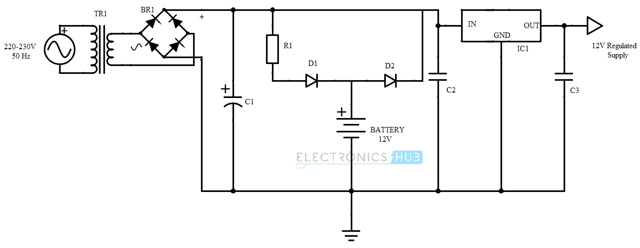
The circuit operation can be divided into three topologies. They are AC – DC conversion, Battery charging circuit and DC – AC conversion (Inverter). The input from the mains is given to a step down transformer i.e. the 230V AC supply is converted to 12 – 15 V AC supply.
The transformer should be properly chosen with appropriate current rating. A transformer of at least 2A current rating should be selected and for higher capacity loads, 8A transformer is required.
The stepped down AC voltage is applied to a bridge rectifier to convert it to DC of 12 – 15 V. A capacitor is used in parallel to the bridge rectifier to filter any AC signals. The combination of R1 and D1 provide a charging path for the battery.
The use of D2 is to provide a current limit for the batter while charging from the supply. If D2 is absent, the battery will charge from the supply without any current limit and this might result in overheating and damaging the battery.
A 12V voltage regulator is used to provide a regulated voltage for the inverter. An LM 7812 is used for this purpose.
The input to the voltage regulator can be from two sources viz. battery and mains. In case of a power failure, the voltage regulator automatically gets its input supply from the battery and as there are no switches, there will be no interruption to the supply of the inverter (DC – AC converter).
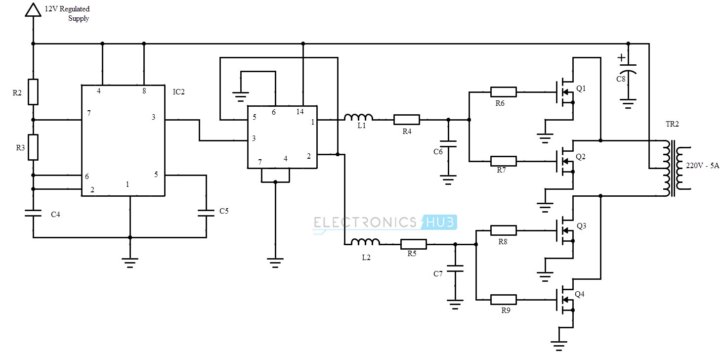
In order to convert the regulated DC voltage to AC, we need to generate an alternating signal and the easiest way to produce an alternating signal is to generate a Square wave using the 555 timer. An LM 555 timer IC is used to generate a square wave and the supply to the timer is given from the output of the voltage regulator, which is 12V.
The frequency of the square wave should be 50 Hz (as the supply frequency is 50 Hz). Resistor R3 and C4 ensure that the output frequency is around 50 Hz. This process is equivalent to conversion of 12 V regulated DC to 12 V AC.
The output of the timer IC, which is a square wave, is given to a D flip – flop IC. CD 4013 is the IC of a Dual D flip – flop and both the inverting and the non – inverting output of the D flip – flop is taken. We need to take both the inverting and non – inverting outputs as they have to be applied to the output transformer.
We need to supply an alternating sinusoidal wave of 50 Hz for the electrical and electronic devices to work properly. The output here is a square wave. Hence, in order to convert the square wave to a sine wave, we use the combination of inductor, resistor and a capacitor.
Two sets of the components are required, each for inverting and non – inverting waves. (L1, R4, C6 for non – inverting and L2, R5, C7 for inverting).
In order to drive the primary coil of the step up transformer and to increase the power, we use MOSFETs. The MOSFETs used in the circuit are IRF540, which are N-channel MOSFET’s that are rated at 100V, 27A to 220V.
Two such MOSFET’s are used for inverting and non-inverting outputs from the D flip – flop so that the power can be increased to 200W. The MOSFET’s drive the output transformer, which converts the 12 V AC to 220 – 230V AC.
Guidelines and Instructions
- The uninterruptible power supply circuit described here can be used for a load up to 200W.
- In order to increase the output power capacity, the input transformer should be able to deliver a current of 8A (minimum 2A current is required from the transformer).
- The MOSFETs used are at a capacity of 100V and 28A. More efficient MOSFETs and more number of MOSFETs can be used to increase the power output.
- MOSFETs generate a lot of heat and necessary heat sink must be used.
- In order to protect the circuit from high voltages and currents, a fuse (of minimum 2A) must be used at the output of the bridge rectifier and also after the voltage regulator.
- An LED in series with a resistor can be used in series with R1 to indicate the source of the power. Additionally, a diode D3 (IN4001) must be placed R1 and input of the voltage regulator. This setup ensures that the LED glows only when the source is mains and the diodes D1 and D3 ensure that the LED doesn’t glow due to battery.
- An efficient battery charging circuit can be found here,automatic-battery-charger-circuit
- A simple circuit to indicate the battery level is shown here,Battery-level-indicator
Applications
- The uninterruptible power supply can be used to power small electrical devices with a maximum power rating of 200W.
- Can be used to power up a PC during power failure.
- Can be used as a backup power source and the duration of the backup can be increased by connecting more than one battery.

2 Responses
Hi to all, how is all, I think every one is getting more from this site,
and your views are fastidious in support of new
users.
The detailed explanations are so precise and informative thanks and keep it up